WR1000-UM-251–01–9380 6 – 27
6. INSPECTION AND CHECK PROCEDURES
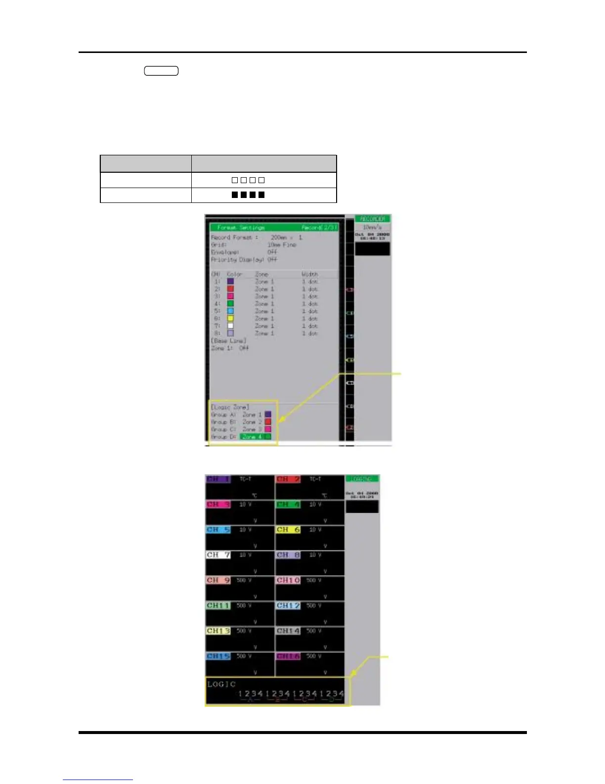
(2) Press the
RECORD
key twice to open the Format Settings window (shown in Fig. 6-3-3), then specify the
Logic Zone parameters.
(3) Press the main control panel’s MODE key to select LOGGING as the measurement mode.
(4) Check that the measured results conform to those in the “Results” column in the table below when each
specified voltage is input to the logic input terminals.
Table 6-3-1. When the Threshold level is +1.4V (TTL)
Input voltage Results (A, B, C, and D)
1 V
(
LLLL
)
2 V
(
HHHH
)
Fig. 6-3-2. Format Settings window
Fig. 6-3-3
Logic Zone settings
Logic display area
(see NOTE below)