WR1000-UM-251–01–9380 3 – 6
3. DISASSEMBLY AND REASSEMBLY
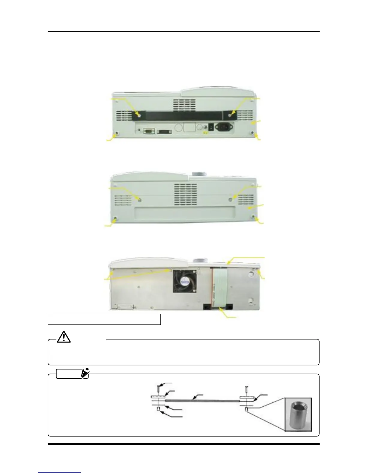
3.3 Replacing the Control Panel Unit
To replace any component of the control panel, you must first remove the control panel unit from the main unit
as described below.
(1) Remove the molded cover on the power unit side (the rear cover).
Fig. 3-3-1
(2) Remove the molded cover at the front of the main unit (the front cover).
Fig. 3-3-2
(3) Remove the six screws and disconnect a cable from one connector, then remove the control panel unit.
Fig. 3-3-3
CAUTION
When changing the orientation of the main unit, do not hold the recorder by the control panel unit after
removing the screws from one side only.
NOTE
Mount the handle as shown in
the figure below. Moreover, the
tapered end of the handle boss
should be on top.
M4L18 countersunk-
head screw
M4L18 countersunk-
head screw
Rear cover
M3L4 binding-head
screw
M3L4 binding-head
screw
M4L5 binding-head
screw
M4L5 binding-head
screw
Front cover
M3L4 binding-head
screw
M3L4 binding-head
screw
Handle plate
M4L18 countersunk-head screw
Handle cover
Handle
Lower handle plate
Handle boss
Fig. 3-3-4
Remove by grasping
these side grips.
M3L4 binding-head
screws
M3L4 binding-head
screws
Control panel unit
* Also remove three screws from the other side.