WR1000-UM-251–01–9380 6 – 29
6. INSPECTION AND CHECK PROCEDURES
Check Procedure
(1) Input either +12 or +24 VDC to the DC IN terminal, depending on the model number of the WR1000 main
unit.
(2) Turn on the main unit’s DC Power switch and check that the WR1000 is properly booted.
(3) Input 100 V (200 V) to the main unit’s AC line inlet, then turn on the AC Power switch.
(4) Turn off the DC Power switch and check that the WR1000 is running on the AC power supply alone.
(5) Turn the DC Power switch back on and turn off the AC Power switch.
(6) Check that the WR1000 has switched to operation on the DC power supply without the TFT going off.
(7) At the same time, check the signal level of the REMOTE OUT signal (see Subsection 6.2.8, “REMOTE
Interface Operation”).
(8) With the WR1000 running on the DC power supply, perform recording (printing) at a Chart Speed setting
of 10mm/s and check that the printing operation is normal.
6.3.5 Internal HDD/MODD Operation
The following inspection tests an internal HDD (Hard Disk Drive) or internal MODD (Magneto-Optic Disk
Drive). If an external memory device has been installed, please remove it first.
Preparations
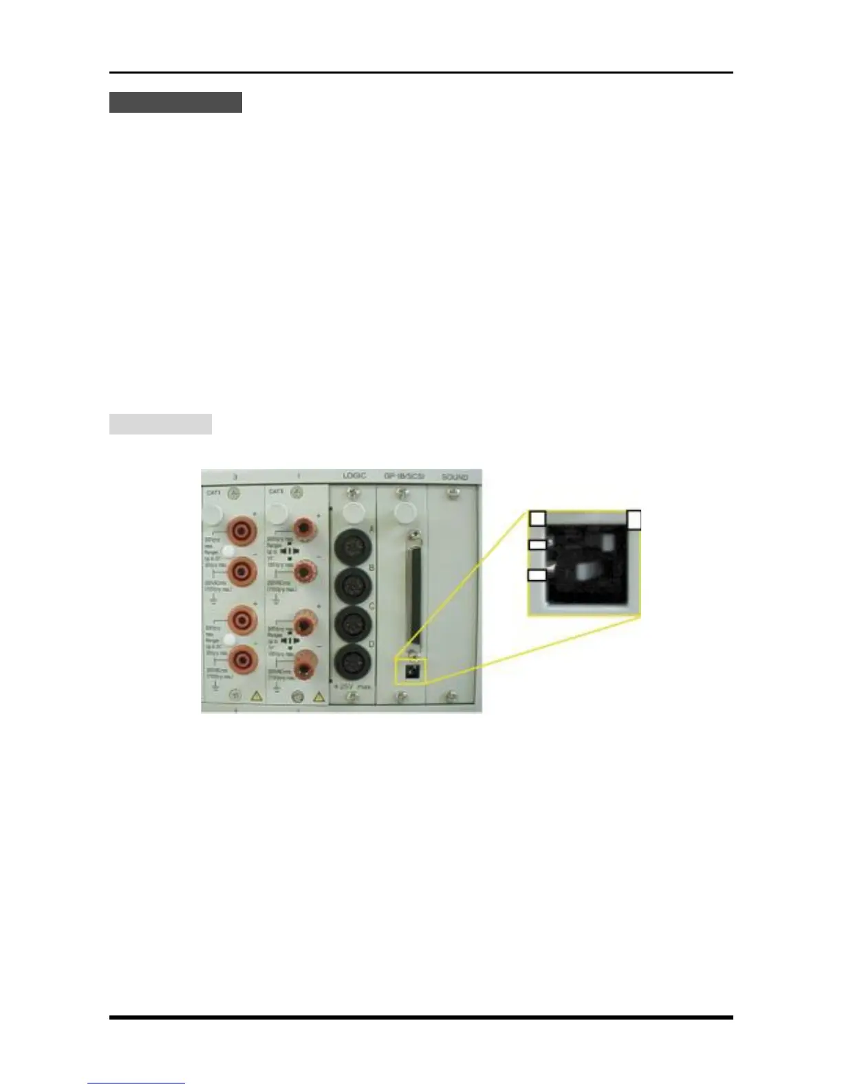
(1) Check the position of the two switches that determine the Terminator setting for the SCSI interface.
Fig. 6-3-6
Confirm that the two switches shown above are set as follows.
1 : ON
2 : ON
ON
OFF
12