WR1000-UM-251–01–9380 6 – 30
6. INSPECTION AND CHECK PROCEDURES
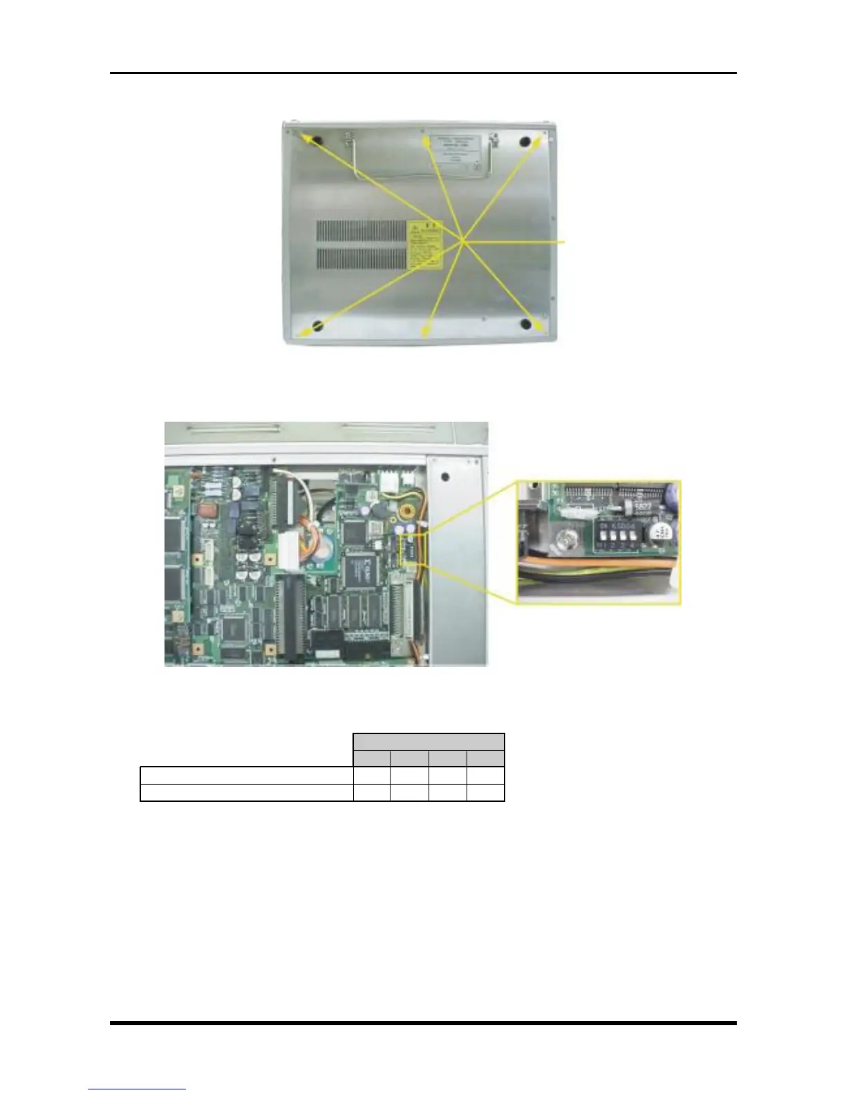
(2) Unfasten the six screws, then remove the bottom plate.
Fig. 6-3-7
(3) Check that the four bits of DIP switch S1 on the SCSI control board are properly set.
Fig. 6-3-8
Table 6-3-4
S1
1234
HDD only or MODD plus HDD OFF OFF OFF OFF
MODD only ON ON ON ON
(4) Turn on the WR1000.
(5) The device ID and part number of the connected memory device(s) are displayed while the WR1000 is
being booted, so check that the device IDs are as follows.
ID0 : Internal HDD
ID1 : Internal MODD
ID2 :
| External HDD, MODD, or Zip drive
ID6 :
M3L5 countersunk-head
screws