WR1000-UM-251–01–9380 3 – 26
3. DISASSEMBLY AND REASSEMBLY
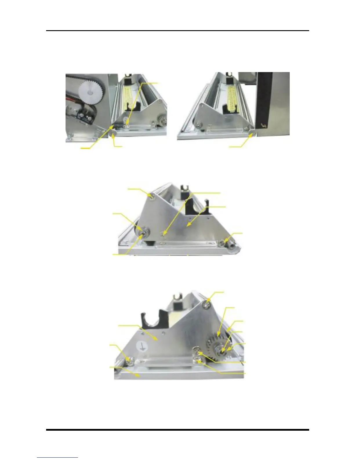
3.5.3 Replacing the Platen
(1) Remove the printer unit (see Subsection 3.5.1, “Replacing the Thermal Printhead”).
(2) Remove the right and left screws and the ground line, then remove the printer cover assembly.
Fig. 3-5-13
(3) Remove the components indicated in the figure below from the right cover side plate.
Fig. 3-5-14
(4) Remove the components indicated in the figure below from the left cover side plate, remove the left cover
side plate from the printer cover assembly, then replace the platen.
Fig. 3-5-15
Platen
BB SMR84ZZ, NSK
E ring (3-mm diameter)
M3L6 countersunk-head
screw
M3L4 binding-head screw
Left cover side plate
M3L6 binding-head
screw
Printer cover
M3L6 countersunk-head screw
Drum gear
M3L3 setscrews × 2
M3L6 countersunk-head screw
E ring (3-mm diameter)
BB SMR84ZZ, NSK
M3L6 countersunk-head screw
Right cover side plate
M3L6 binding-head screw
M3L6 countersunk-
head screw
Ground lead
M3L6 binding-head screw
M3 star washer
M3L6 countersunk-
head screw