WR1000-UM-251–01–9380 6 – 17
6. INSPECTION AND CHECK PROCEDURES
NOTE
Regardless of the SPAN settings, the Trigger level setting will be ±100% of the selected Range setting.
Table 6-2-6. Example when the Range setting is 5V
(5) Check the memory trigger operation for each channel by successively changing the CH settings at the
Trigger Settings window and then repeating Steps (3) and (4) for the selected channel.
(6) At the Memory Settings window, change the Capture Block setting to 2.
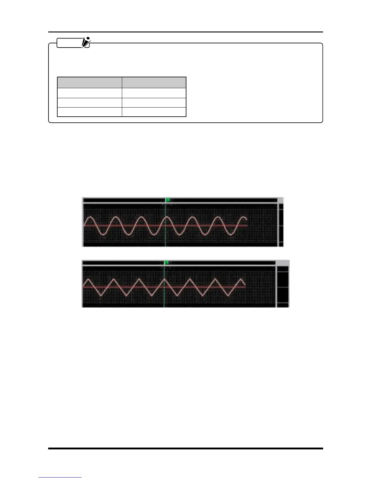
(7) Use the oscillator to input triangular waves of 5-Hz frequency (or 2-Hz frequency if optional memory is
installed) to the selected channel.
(8) After repeating Step (3), check that sine waves were captured in Block No. 1 and triangular waves were
captured in Block No. 2.
Capture Block 1
Fig. 6-2-22
Voltage level Trigger level
+5 V +100%
0 V 0%
–5 V –100%
Capture Block 2