WR1000-UM-251–01–9380 6 – 16
6. INSPECTION AND CHECK PROCEDURES
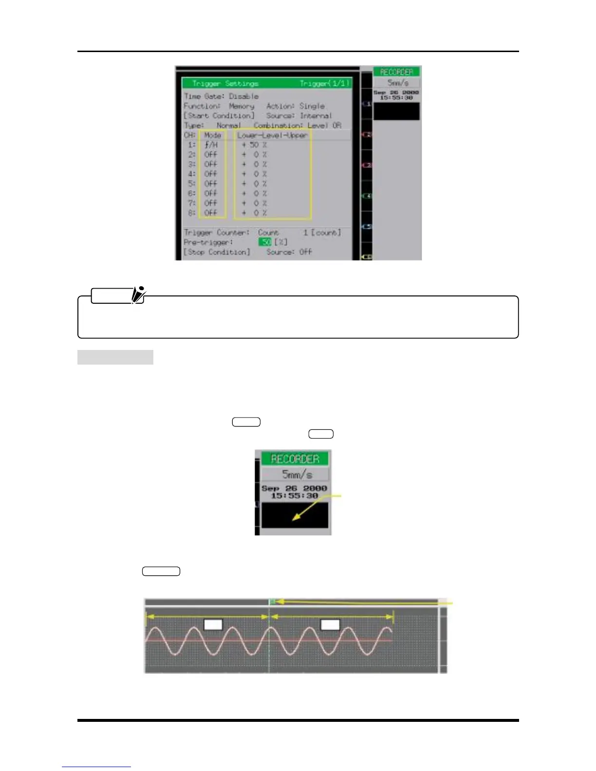
Fig. 6-2-19. Trigger Settings window
NOTE
Specify the Mode and Lower-Level-Upper settings separately for each channel. Also set the Mode
setting to Off for any channel that you do not wish to measure.
Measurement
(1) Set the Capture Block setting (Memory Settings window) and Replay Block setting (Data Replay Settings
window) to 1.
(2) Using the oscillator, input sine waves of 5-Hz frequency (2-Hz frequency if optional memory is installed)
to each channel.
(3) Press the main control panel’s
START
key to initiate measurement. When the “Finished” message
appears at the simplified message area, press the
STOP
key to terminate measurement.
Fig. 6-2-20
(4) Press the
MEM. OUT
key to output the data captured in memory, then check the accuracy of the position
where the trigger was activated and whether the data was accurately captured in memory.
Fig. 6-2-21
Simplified message area
Trigger mark