WR1000-UM-251–01–9380 3 – 18
3. DISASSEMBLY AND REASSEMBLY
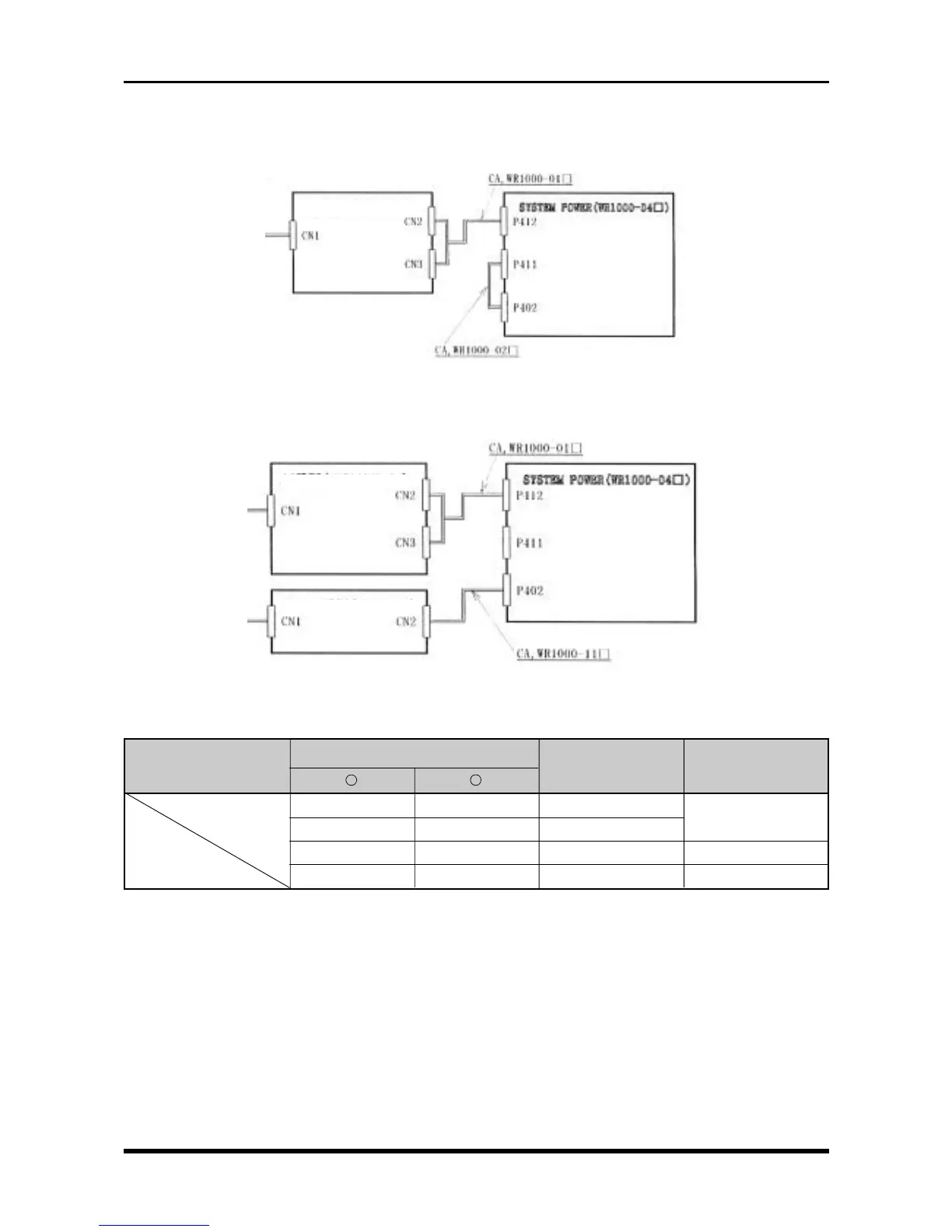
(2) Voltage check
With the 8-channel model
Fig. 3-4-2
With the 16-channel model
Fig. 3-4-3
Table 3-4-2. Voltage check
Connector pin no.
Checkpoint
Measurement range Remarks
+
-
TP1 TP2 +21.6 to +26.4 V +24 V
TP3 TP2 +11.4 to +12.6 V +12 V
TP4 TP2 +4.9 to +5.1 V +5 V
TP6 TP2 +3.46 to +3.12 V +3.3 V
AC input
AC input
AC input
AC power (ZWS150PF-24)
AC power (ZW150PF-24)
16-channel AC power (ZWS50-24)