WR1000-UM-251–01–9380 3 – 9
3. DISASSEMBLY AND REASSEMBLY
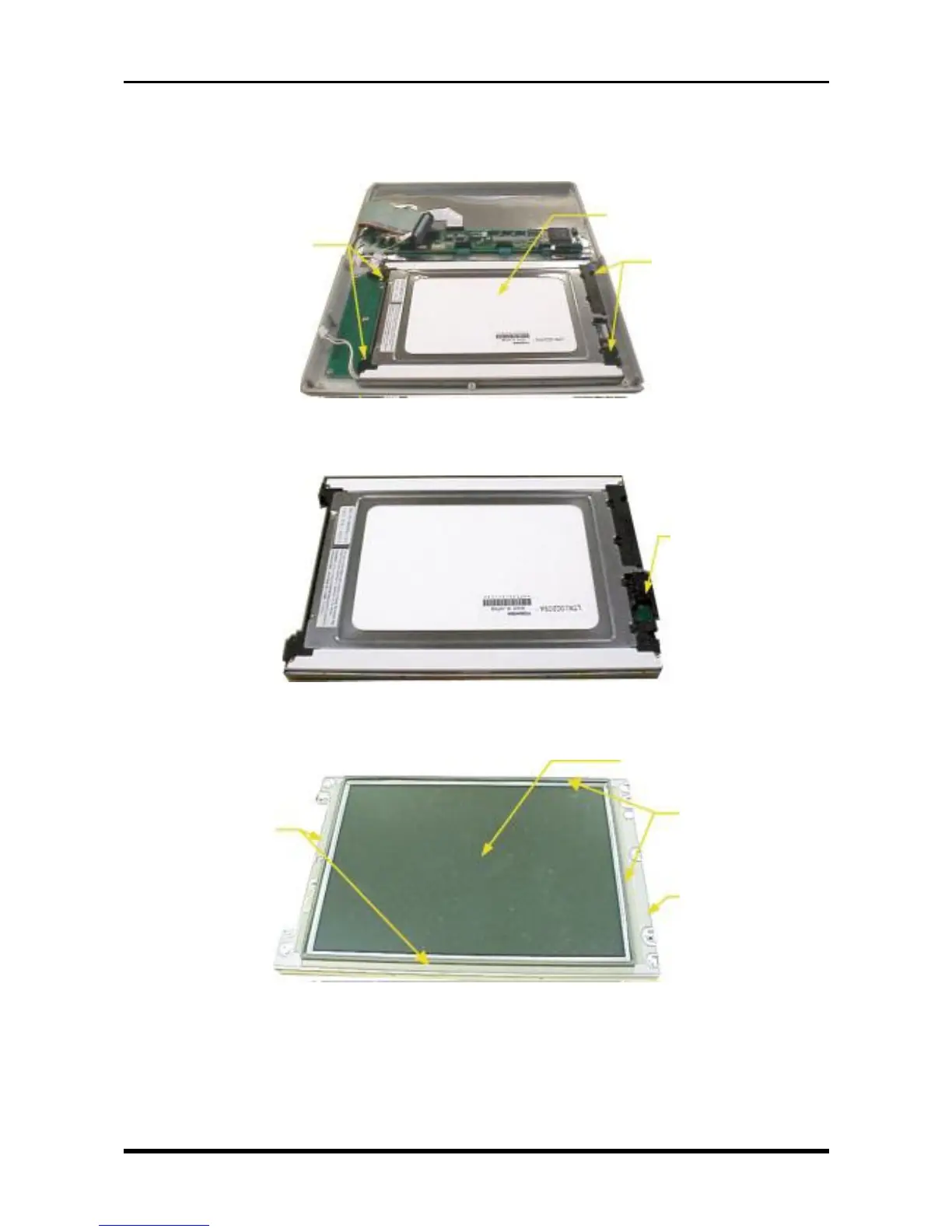
(3) Remove the four screws, then remove the LCD assembly.
* To differentiate a main unit with an additional LCD board holder plate due to a design modification, two
of the four screws are longer.
Fig. 3-3-9
(4) Remove the LCD relay board.
Fig. 3-3-10
(5) Peel off the Nitoflon tape, remove the LCD protective plate assembly, then replace the LCD.
Fig. 3-3-11
LCD relay board
M3L6 binding-head screws
M3L6 binding-head screws
*M3L15 binding-head screws
+ coiled bushing
LCD
assembly
Nitoflon tape
LCD protective plate assembly
Nitoflon tape
LCD