WR1000-UM-251–01–9380 6 – 5
6. INSPECTION AND CHECK PROCEDURES
Measurement
(1) Turn on the printer.
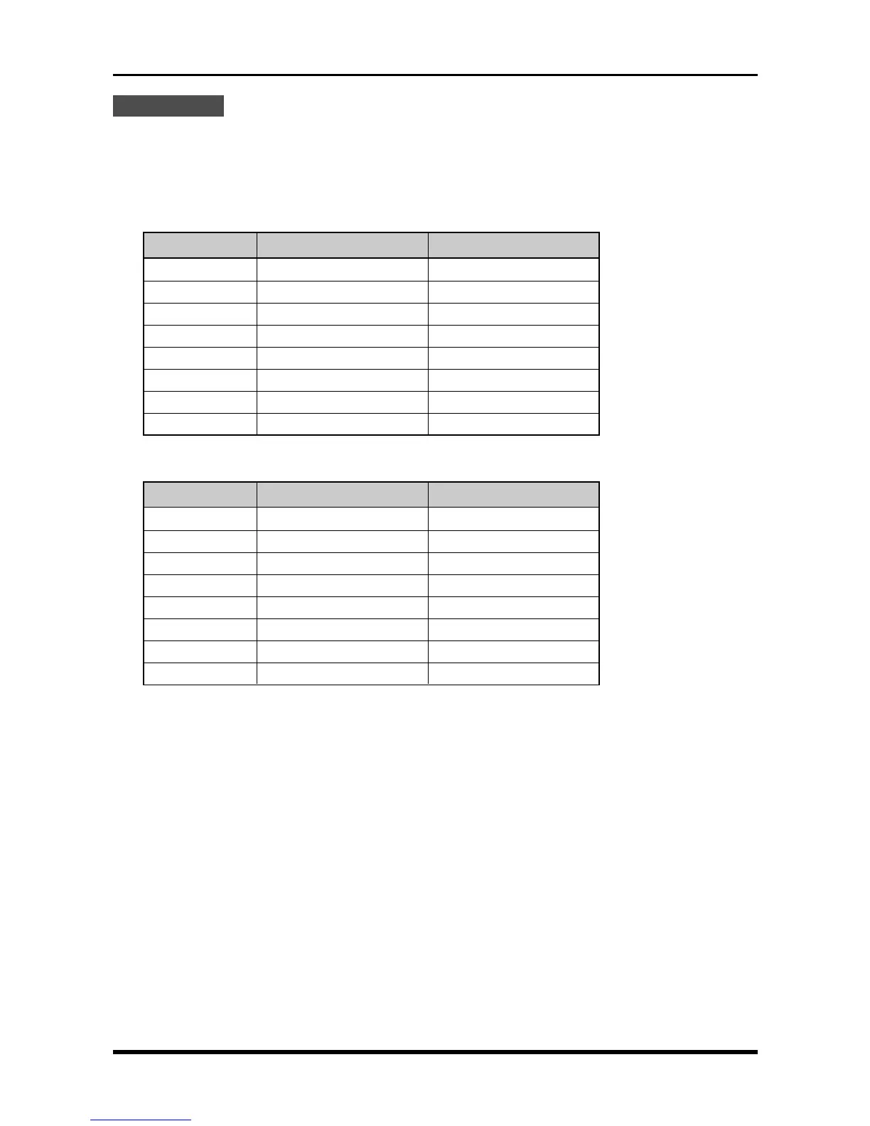
(2) Use the voltage generator to successively input the reference voltage signals for each range according
to the table below, then check that the printed level of measurement is within the rating. (For each
RANGE setting, conduct measurement for about 10 seconds.)
Table 6-2-1. V amp: voltage precision ratings
Table 6-2-2. M amp: voltage precision ratings
RANGE setting Reference voltage Rating (±0.2% of F.S.)
50 mV 50.00 mV 49.90 to 50.10 mV
100 mV 100.0 mV 99.8 to 100.2 mV
200 mV 200.0 mV 199.6 to 200.4 mV
500 mV 500.0 mV 499.0 to 501.0 mV
1 V 1.000 V 0.998 to 1.002 V
2 V 2.000 V 2.996 to 2.004 V
5 V 5.000 V 4.990 to 5.010 V
500 V 500.0 V 499.0 to 501.0 V
RANGE setting Reference voltage Rating (±0.2% of F.S.)
20 mV 20.00 mV 19.96 to 20.04 mV
50 mV 50.00 mV 49.90 to 50.10 mV
100 mV 100.0 mV 99.8 to 100.2 mV
200 mV 200.0 mV 199.6 to 200.4 mV
500 mV 500.0 mV 499.0 to 501.0 mV
1 V 1.000 V 0.998 to 1.002 V
2 V 2.000 V 2.996 to 2.004 V
200 V 200.0 V 199.6 to 200.4 V