WR1000-UM-251–01–9380 3 – 23
3. DISASSEMBLY AND REASSEMBLY
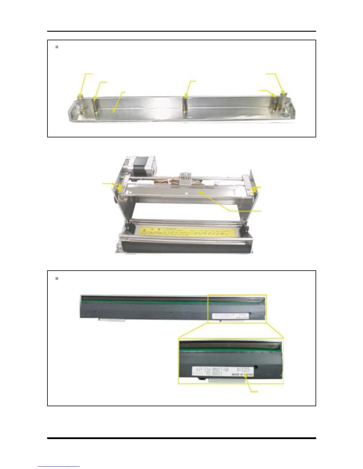
When removing the head pressure support, this component applies pressure on the thermal printhead
using the two types of screws shown below (five screws total). When removing the head pressure
support, be careful not to lose these springs.
Fig. 3-5-7
(8) Remove two head bushings each from the right and left sides, then replace the thermal printhead.
Fig. 3-5-8
After the thermal printhead is replaced, its resistance value will be written in the area shown below.
Be sure to make a note of the value because it will be needed during the Setup operation.
Fig. 3-5-9
Resistance value
Compression spring C-166
Compression spring DC-515
Head pressure support
Compression spring C-166
Compression spring DC-515
Compression spring DC-515
Head bushing
Thermal printhead +
contact adjustment plate
Head bushing