WR1000-UM-251–01–9380 6 – 2
6. INSPECTION AND CHECK PROCEDURES
*
1
Regarding the testing time, raise the voltage to the test voltage within two seconds, then sustain that value for two more
seconds.
*
2
Condition 1: After setup, measure the temperature in the same setup status in the room where setup was conducted.
Condition 2: Measure the temperature under conditions that vary with the setup status (main unit, measurement site,
insertion slot).
* Nos. 15 through 20 apply to optional devices.
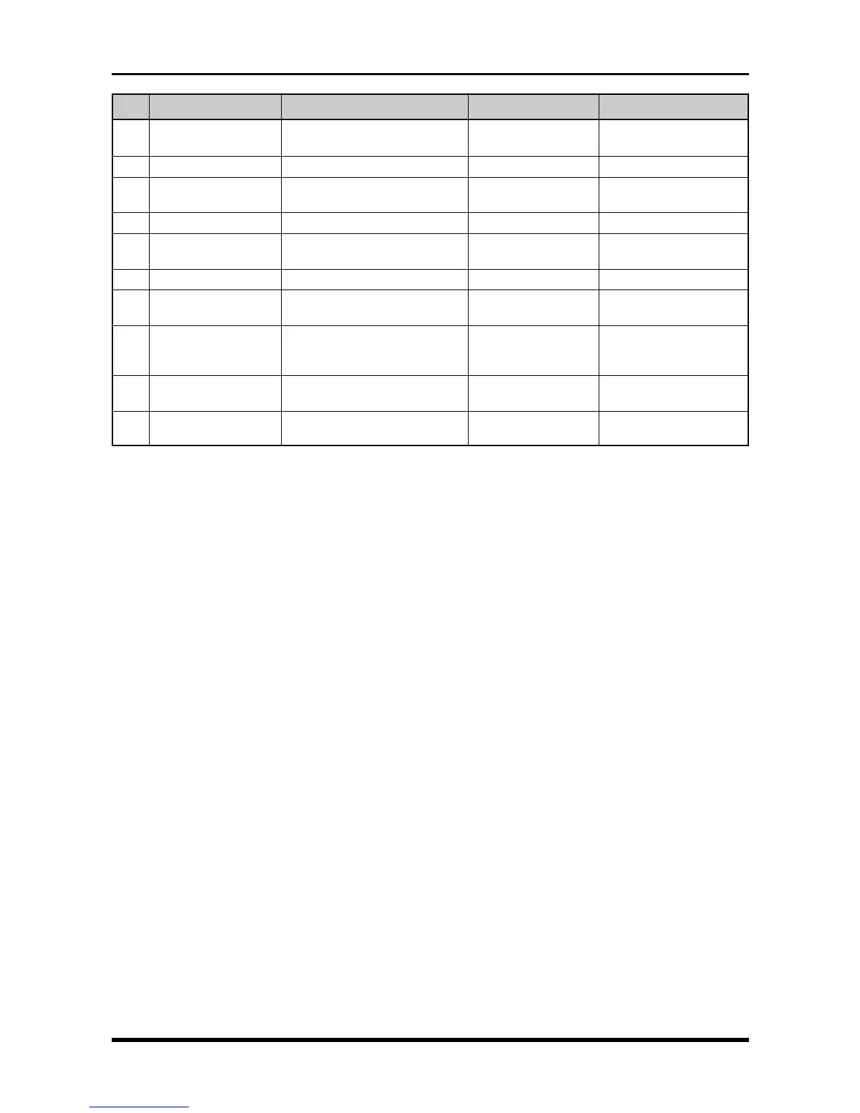
Category
Chart feed precision
Slant of chart feeding
Printing performance
Miscellaneous
GP-IB interface
Logic amp
Expansion memory
DC drive
Internal HDD/MODD
operation
SCSI interface
Inspection/check standard
±1.7%
within ±1.5 mm
Proper operation at 10mm/s and
200mm/s
Proper operation
Proper operation
Proper operation
Proper capture of signals in
memory
Proper operation
Proper operation
Proper operation
Related blocks
Thermal printhead board
Printer unit
Printer unit
Thermal printhead board
Printer unit
Main control board
GP-IB board
Main control board
Logic amp
Expansion memory board
AC/DC select board
DC power board
DC input unit
HDD, MODD, SCSI
control board
SCSI control board
SCSI power board
No.
11
12
13
14
15
16
17
18
19
20
Product standard
within ±2% + 0.5 mm
Same as left
Same as left
Same as left
Same as left
Same as left
Same as left
Same as left
Same as left
Same as left