WR1000-UM-251–01–9380 3 – 42
3. DISASSEMBLY AND REASSEMBLY
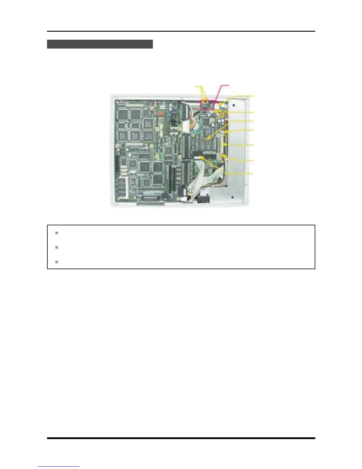
Replacing the SCSI Control Board
(1) Remove the bottom plate (see Subsection 3.6.1, “Replacing the 16-CH Control Board”).
(2) Unfasten the two screws in the SCSI power board.
(3) Unfasten the three screws, disconnect the three cables from their connectors, then replace the SCSI
control board.
Fig. 3-9-10
If the MODD (Hard Disk Drive) is installed, also disconnect the two cables from connectors P123 and
P126 (see Fig. 3-9-6).
Confirm that the bits of the SCSI control board’s DIP switch are set to the same positions as before the
SCSI control board was replaced.
The SCSI cable for the HDD is very slender, so be careful not to cut it or otherwise damage it.
P125
M3L4 binding-head screw
SCSI control board
M3L4 binding-head screw
P122
M3L4 binding-head screw
P124
M3L4 binding-head screw
SCSI power board