WR1000-UM-251–01–9380 3 – 4
3. DISASSEMBLY AND REASSEMBLY
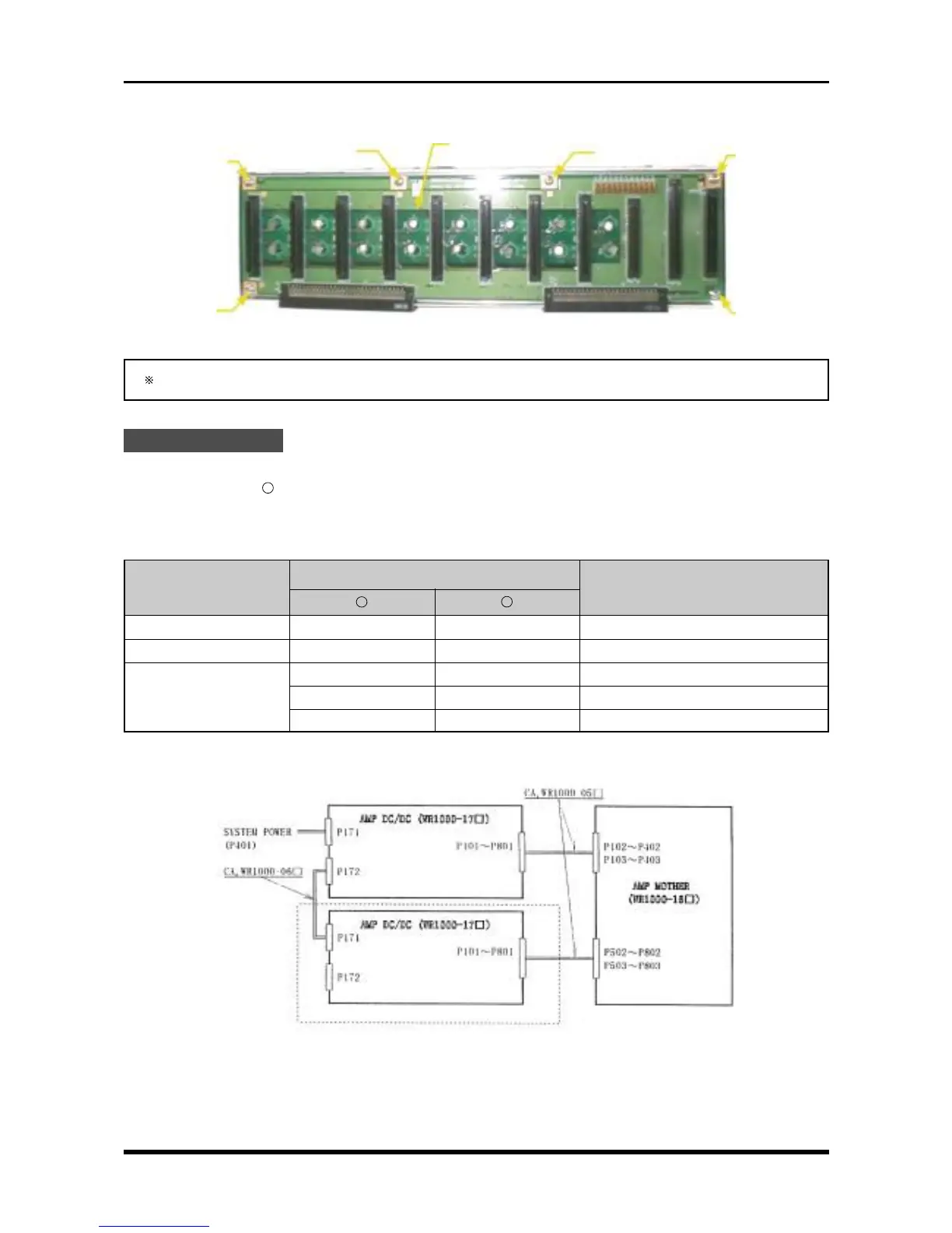
(4) Remove the six screws, then replace the amp mother board.
Fig. 3-2-8
During reassembly, be sure to connect each cable to its proper connector.
Check Procedures
(1) Short check
Regarding the “
-
” mark as the minus side of the multimeter, use the multimeter to check the voltage
between the connector pins specified in the following table.
Table 3-2-1. Short check
Connector pin no.
Checkpoint
Remarks
+
-
P102 to P802 1 2 +5 V (amps with odd channel nos.)
P103 to P803 1 2 +5 V (amps with even channel nos.)
91 to 94 99 to 100 +5 V
P3 95 to 96 99 to 100 +3.3 V
97 to 98 99 to 100 +3.3 V1
(2) Voltage check
Fig. 3-2-9
Amp mother board
M3L4 binding-
head screw
M3L4 binding-
head screw
M3L4 binding-
head screw
M3L4 binding-
head screw
M3L4 binding-
head screw
M3L4 binding-
head screw
Absent from the 8-channel model