Home
GW Instek
AC Power Distribution
APS-7000 Series
Page 36
GW Instek APS-7000 Series - Page 36
193 pages
Manual
To Next Page
To Next Page
To Previous Page
To Previous Page
Loading...
APS-7000 Series User Ma
nual
36
APS-7100
3
2
CAUTION
F
or t
he APS-7100, there
is a single bank f
or the
input and output terminals. E
nsure the correct
terminals are connected. T
he APS-7
050, APS-7200
and APS-7300 have
a
dedicat
ed ba
nk of output
terminals on the rear pane
l.
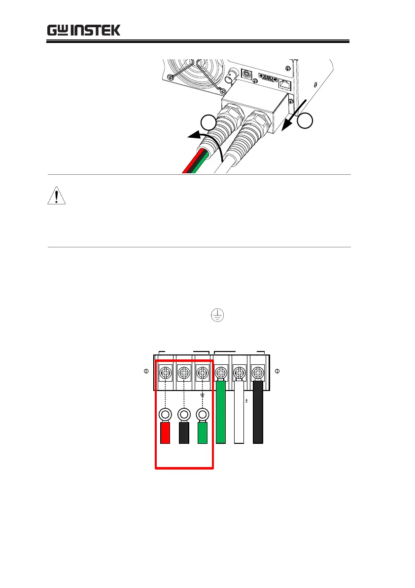
Installation
4.
Connect the output AC
power cord
wires to
the AC output ter
minals.
Black
Neutral (N)
Green
GND (
)
Red
Line (L)
APS-7100
OUTPUT
INPUT
L
N
N
L
1
1
5
/ 230
V
15%
Line
Neutral
Ground
Ground
Neutral
Line
APS-7100 shown. T
he input terminals are a
lready
connected and shows
which output terminals a
re
to be connected.
35
37
Table of Contents
Main Page
Table of Contents
3
Safety Instructions
4
Etting Started
8
APS-7000 Series Overview
9
Series Lineup
9
Operating Area
9
Main Features
11
Accessories
12
Getting Started
9
Appearance
14
Front Panel
14
Rear Panel
19
Status Bar Icons
24
Peration
26
Default Chapter
27
Operation
27
Set up
28
Line Voltage Removal and Installation for APS-7100
28
Filter Installation
31
Power up
33
Output Terminals
34
Wire Gauge Considerations
39
Installing the Optional Hardware Modules
41
Installing Optional Software Modules
43
Using the Rack Mount Kit
48
How to Use the Instrument
50
Reset to Default Settings
54
View System Version and Serial Number
55
LCD Configuration
56
USB Driver Installation
57
Basic Operation
60
Setting the Voltage Range
60
Setting the Voltage Limit
61
Setting the Output Voltage
62
Setting the Frequency Limit
64
Setting the Output Frequency
65
Setting the Peak Current Limit
66
Setting the Current RMS Level
70
Setting the On/Off Phase
73
Alarm Clear
74
Display Modes
75
Panel Lock
77
Turning the Output on
78
Local Sense
79
Using the Remote Sense (APS-7200 and APS-7300 Only)
79
Remote Sense
80
Advanced Settings
82
Surge/Dip Control
82
Ramp Control
85
Miscellaneous
88
T Ipeak, Hold
88
Power on Output
90
Buzzer
91
SCPI Emulation
92
Remote Sense (APS-7200 and APS-7300 Only)
93
Trigger
95
Trigger Control Settings
95
Preset Settings
100
Save Preset Settings to Local Memory
100
Load Preset Settings to Local Memory
101
Manage Preset Settings
102
Arbitrary Waveform Function
104
ARB Mode Overview
105
Selecting an ARB Waveform
109
Test Mode Function
112
Simulate Mode Overview
114
Simulate Settings
118
Recall a Simulation from Local Memory
121
Save a Simulation to Local Memory
121
Manage Simulation Settings
122
Running a Simulation
124
Sequence Mode Overview
126
Sequence Settings
130
Recall a Sequence from Local Memory
134
Save a Sequence to Local Memory
134
Manage Sequence Settings
135
Running a Sequence
137
Program Mode Overview
139
Recall a Program from Local Memory
146
Save a Program to Local Memory
146
Manage Program Settings
147
Rear Panel Signal Outputs
149
Ommunication
153
Default Chapter
153
Communication Interface
153
Interface Configuration
154
USB Remote Interface - Optional (APS-7050 and APS-7100 Only)
154
RS-232 Remote Interface - Optional
155
RS-232/USB Remote Control Function Check
158
Using Realterm to Establish a Remote Connection
159
Configure GPIB Interface - Optional
162
GPIB Function Check
163
Configure Ethernet Connection
167
Web Server Remote Control Function Check
169
Socket Server Function Check
170
Faq
175
Appendix
177
Firmware Update
177
APS-7000 Default Settings
179
APS-7000 Specifications
181
APS-7000 Dimensions
187
Declaration of Conformity
191
Index
193
Faq
177
Other manuals for GW Instek APS-7000 Series
Programming Manual
152 pages
Related product manuals
GW Instek APS-7050
193 pages
GW Instek APS-7100
193 pages
 Loading...