APS-7000 Series User Manual
96
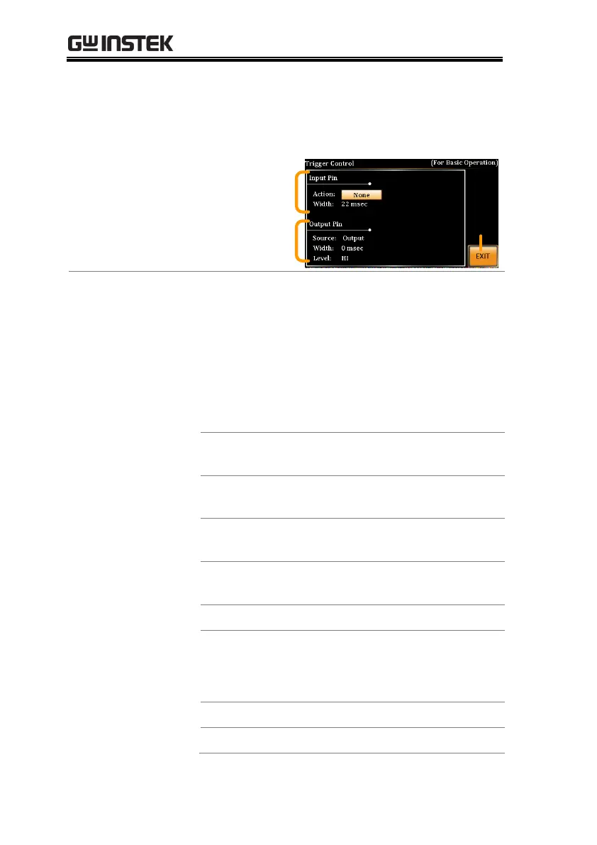
2. The trigger control settings appear. The
settings are divided into Input Pin and Output
Pin.
Trigger input
settings
Exit
Trigger output
settings
1. The Input Pin settings configure what action is
taken when the Trigger In pin on the J1
connector is high.
2. Go to the Action setting using the scroll wheel
and press Enter. Choose what will happen
when the Trigger In pin is pulsed high(+5V)
and then press Enter to confirm.
No action is taken. Remote trigger
commands are accepted.
Turns the output on or off when
triggered.
Sets a user-defined voltage and
frequency setting when triggered.
Loads a preset setting when
triggered.
Triggers the surge/dip control.
3. Go to the Width setting and set the minimum
pulse width to recognize the trigger input
pulse.
Minimum pulse width (5ms)
 Loading...