CONFIGURATION
103
Select coupling mode
Panel operation
1. Press the Channel key.
CH1
2. Press F1 (Coupling)
repeatedly to select the
coupling mode.
Coupling
F 1
Range
DC coupling mode. The whole
portion (AC and DC) of the signal
appears on the display.
Ground coupling mode. The display
shows only the zero voltage level as a
horizontal line. This mode is useful
for measuring the signal voltage with
respect to the ground level.
AC coupling mode. Only the AC
portion of the signal appears on the
display. This mode is useful for
observing AC waveforms mixed with
DC signal.
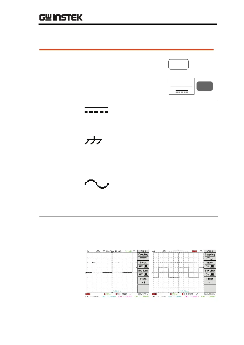
Example
Observing the AC portion of the waveform using
AC coupling
DC coupling
AC coupling

 Loading...


