MEASUREMENT
53
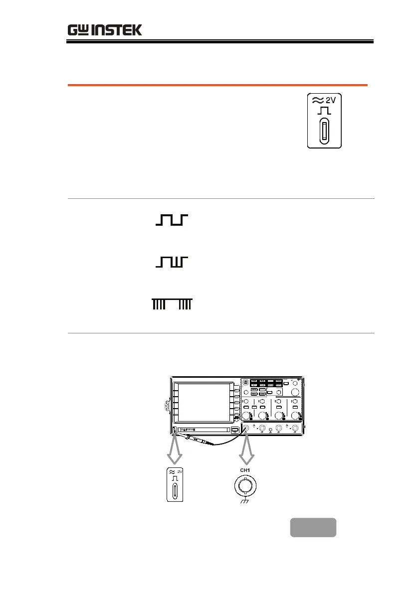
Probe compensation signal
Background
This section introduces how to use
the probe compensation signal for
general usage, in case the DUT
signal is not available. For probe
compensation details, see page159.
Note that the frequency accuracy and duty factor
are not guaranteed. Therefore the signal should
not be used for reference purpose.
Waveform type
Square waveform for probe
compensation. 1k ~ 100kHz, 5% ~
95%.
Demonstration signal to show the
effect of peak detection. See page85
for peak detection mode details.
Demonstration signal to show the
effect of long memory. See page87 for
memory length details.
View
compensation
waveform
1. Connect the probe between the compensation
signal output and Channel input.
Utility
Help
CH1 CH2MATH CH3 CH4
CH1
MENU
HORI
MENU
CH2 CH3 CH4
CAT300V
M
16pF
MAX. 300Vpk
1
CAT300V
M
16pF
MAX. 300Vpk
1
2V
POSITION
HORIZONTAL
TIME/DIV
LEVEL
TRIGGER
VARIABLE
STBYON/
POSITI ON
POSITI ON
POSITION
VERTIC AL
POSITION
GDS-210 4
Digital Storage Oscilloscope
100MHz 1G Sa/s
VOLTS/DIV VOLTS/DIV VOLTS/DIV VOLTS/DIV
2. Press the Utility key.
Utility

 Loading...


