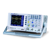
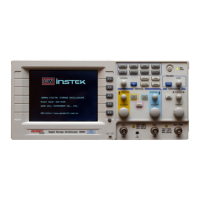
GDS-2000 Series User Manual
112
4. Press F4 (Ext) repeatedly to
select the threshold level for
the external trigger input.
Ext:
TTL
F 4
Range
TTL (1.48V), ECL (1.35V),
User (–12V ~ +12V)
5. Press F5 (Slope/Coupling)
to set the slope and coupling
condition for external
trigger input signal. Note
that this setting does not
affect the trigger source
signal (Channel 1 or 2).
Slope /
Coupling
F 5
 Loading...
