123
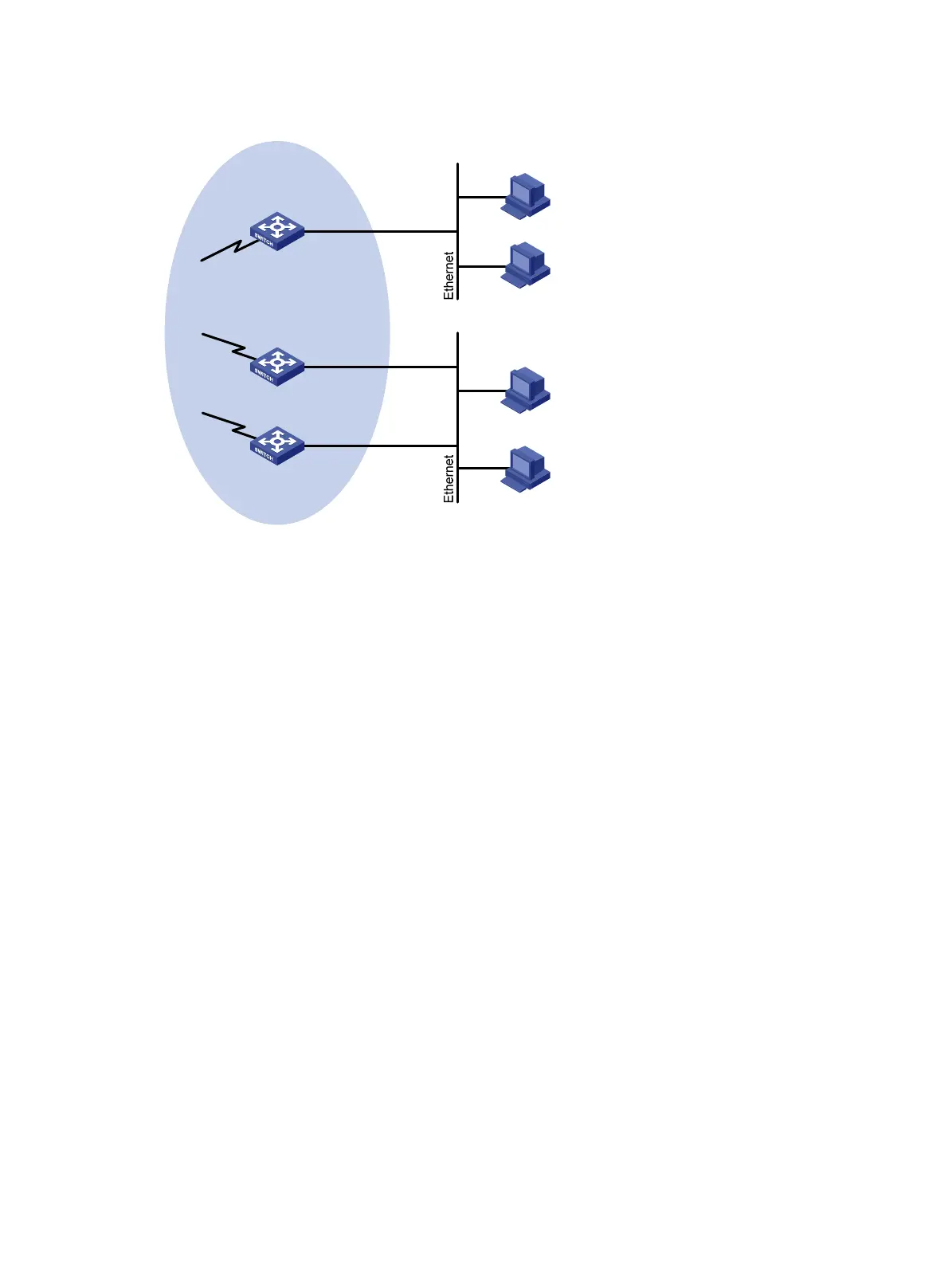
Figure 37 Network diagram
Configuration procedure
1. Configure the IP address and subnet mask of each interface as per Figure 37. (Details not shown.)
2. Configure OSPF on the switches in the PIM network to make sure the switches are interoperable at
the network layer and they can dynamically update their routing information. (Details not shown.)
3. Enable IP multicast routing, and enable PIM-DM and IGMP:
# Enable IP multicast routing on Switch A, enable PIM-DM on each interface, and enable IGMP on
VLAN-interface 100.
<SwitchA> system-view
[SwitchA] multicast routing-enable
[SwitchA] interface vlan-interface 100
[SwitchA-Vlan-interface100] igmp enable
[SwitchA-Vlan-interface100] pim dm
[SwitchA-Vlan-interface100] quit
[SwitchA] interface vlan-interface 101
[SwitchA-Vlan-interface101] pim dm
[SwitchA-Vlan-interface101] quit
# Enable IP multicast routing on Switch B, enable PIM-DM on each interface, and enable IGMP on
VLAN-interface 200.
<SwitchB> system-view
[SwitchB] multicast routing-enable
[SwitchB] interface vlan-interface 200
[SwitchB-Vlan-interface200] igmp enable
[SwitchB-Vlan-interface200] pim dm
[SwitchB-Vlan-interface200] quit
[SwitchB] interface vlan-interface 201
Switch A
Switch B
Switch C
Querier
PIM network
N1
N2
Receiver
Receiver
Host A
Host B
Host C
Host D
Vlan-int100
10.110.1.1/24
Vlan-int200
10.110.2.1/24
Vlan-int200
10.110.2.2/24
Vlan-int101
Vlan-int201
Vlan-int202

 Loading...


