125
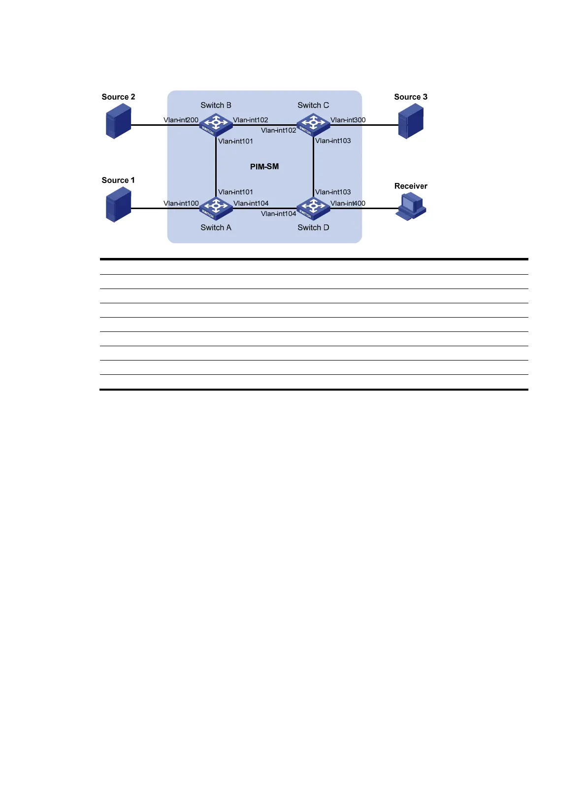
Figure 38 Network diagram
Device Interface IP address
Device
Interface
IP address
Source 1 — 133.133.1.1/24 Source 3 — 133.133.3.1/24
Source 2 — 133.133.2.1/24
Receiver
—
133.133.4.1/24
Switch A Vlan-int100 133.133.1.2/24
Switch C
Vlan-int300 133.133.3.2/24
Vlan-int101 192.168.1.1/24 Vlan-int103 192.168.3.1/24
Vlan-int104 192.168.4.2/24
Vlan-int102 192.168.2.2/24
Switch B Vlan-int200 133.133.2.2/24
Switch D
Vlan-int400 133.133.4.2/24
Vlan-int101 192.168.1.2/24 Vlan-int103 192.168.3.2/24
Vlan-int102 192.168.2.1
24
Vlan-int104 192.168.4.1
24
Configuration procedure
1. Configure the IP address and subnet mask of each interface as per Figure 38. (Details not shown.)
2. Configure OSPF on the switches in the PIM-SM domain to make sure the switches are interoperable
at the network layer and they can dynamically update their routing information. (Details not
shown.)
3. Enable IP multicast routing, enable PIM-SM on each interface, and enable IGMP and IGMP SSM
mapping on the host-side interface:
# Enable IP multicast routing on Switch D, enable PIM-SM on each interface, and enable IGMPv3
and IGMP SSM mapping on VLAN-interface 400.
<SwitchD> system-view
[SwitchD] multicast routing-enable
[SwitchD] interface vlan-interface 400
[SwitchD-Vlan-interface400] igmp enable
[SwitchD-Vlan-interface400] igmp version 3
[SwitchD-Vlan-interface400] igmp ssm-mapping enable
[SwitchD-Vlan-interface400] pim sm
[SwitchD-Vlan-interface400] quit
[SwitchD] interface vlan-interface 103
[SwitchD-Vlan-interface103] pim sm
[SwitchD-Vlan-interface103] quit
[SwitchD] interface vlan-interface 104

 Loading...


