2
Physical architecture
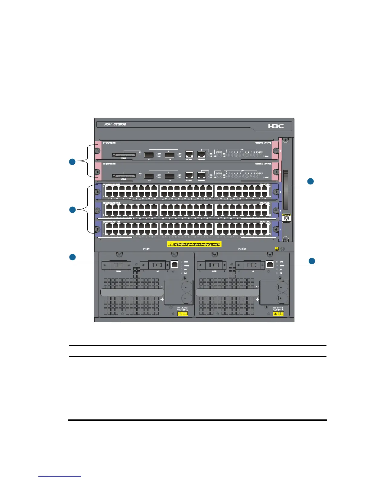
Chassis
The S7500E series consists of a switching and routing processing unit (SRPU) section, line processing unit
(LPU) section, power supply module section, and fan tray section. The following uses an S7503E as an
example.
Figure 2 Front view of the S7503E
1
2
3
3
4
Table 1 Description of the sections of the chassis
Section Description Ordering remarks
①
SRPU section
Provides slots for SRPUs. SRPUs
have pink edges. They must be
inserted in the slots with pink
edges.
SRPUs are required but not shipped with the switch.
• The S7500E series support various types of SRPUs.
You can select them as needed. For more information,
see the chapter “Appendix B Pluggable module
ordering guide.”
• You can install two SRPUs (for active and standby
switchover) for all models of the S7500E series except
the S7503E-S.

 Loading...


