9
Cooling requirements
For adequate heat dissipation, plan the installation site according to the airflow of your switch, and
adhere to the following requirements:
• Leave a clearance of at least 10 cm (3.94 in) around the air intake and exhaust vents.
• The rack for installing the switch has a good cooling system.
• The installation site has a good cooling system.
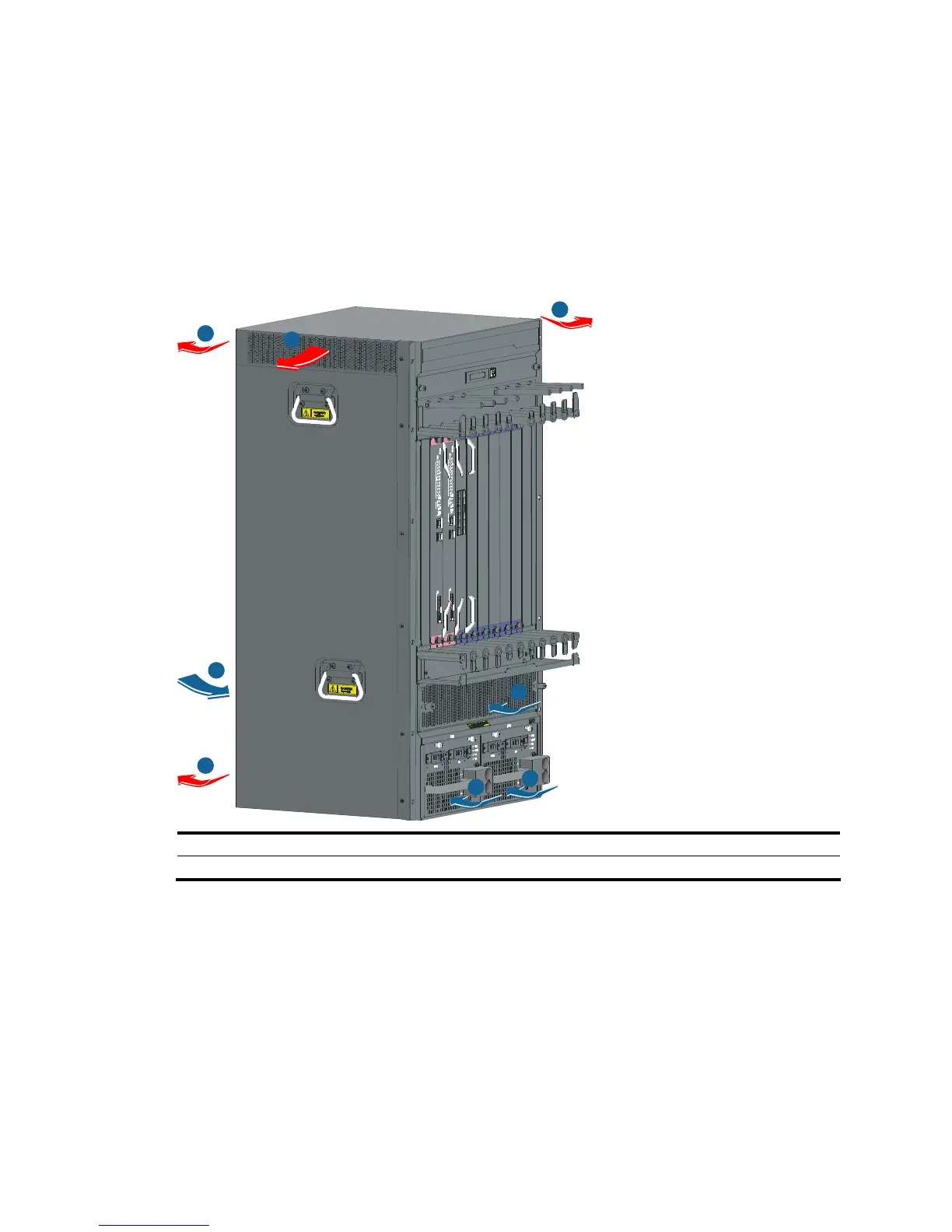
Figure 3 Airflow for the S7506E-V
1
1
2
3
3
4
4
4
1: Air intake for power modules 2: Air exhaust for power modules
3: Air intake for the chassis 4: Air exhaust for the chassis

 Loading...


