to the card status LED (SLOT) on the SRPU of the
switch. If the RUN LED blinks, the card in the slot operates properly. For more information about card
status LED (SLOT), see the chapter “Appendix C LEDs.”
• After the switch is powered on, you can check the card running status at the command line interface
(CLI). For more information, see the chapter “Hardware management and maintenance.”
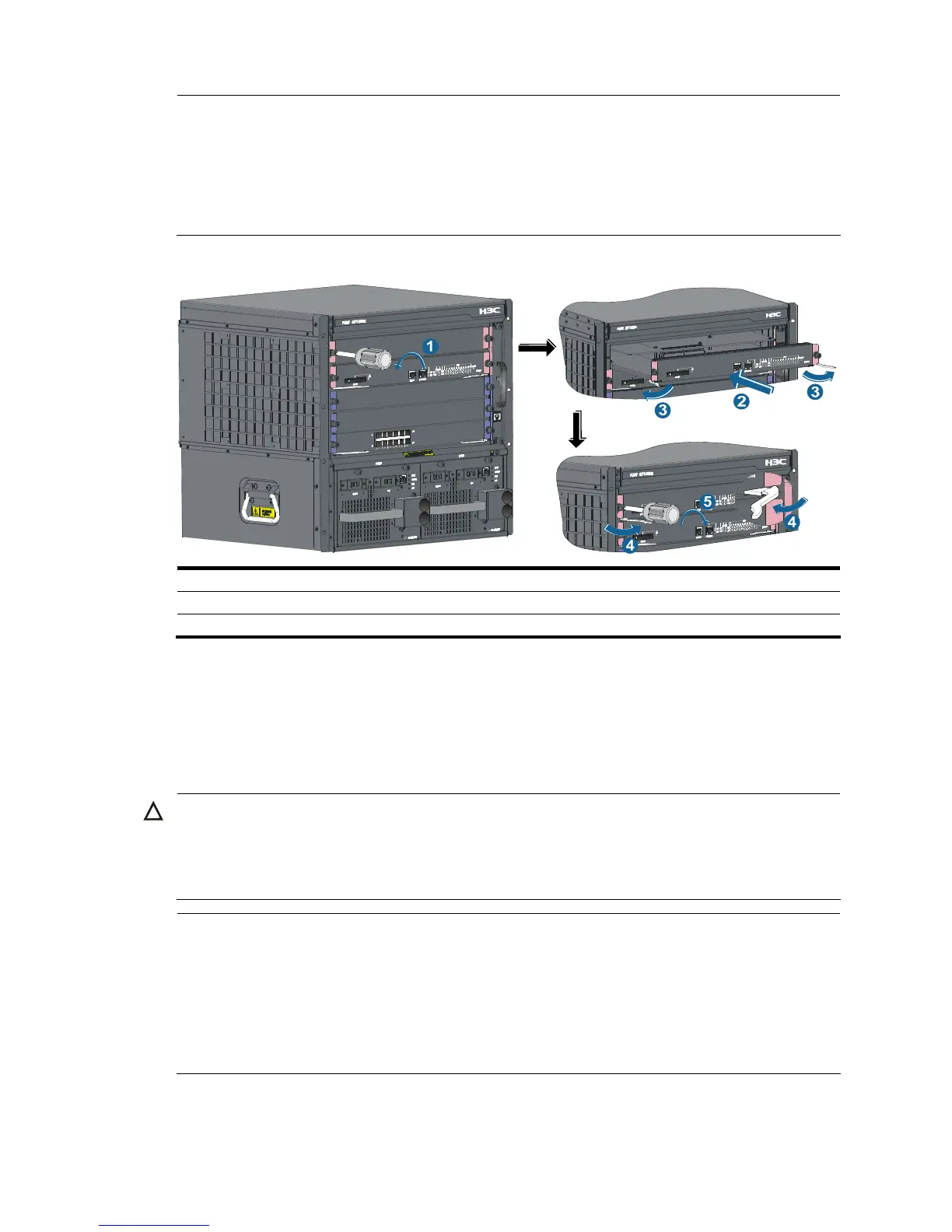
Figure 22 Install a card
1: Remove the blank filler 2: Slide the card into the slot along the guide rails
3: Press the ejector levers on the card outward 4: Press the ejector levers on the card inward
5: Fasten the captive screws
Installing a power module
The S7500E series adopts 1 + 1 power redundancy and supports dual-grid power input. You can select
AC or DC power supply as needed. For more information about optional power modules, see the
chapter “Appendix B Pluggable module ordering guide.”
CAUTION:
• For dual-grid input, the input voltage and frequency for the two grids must the same.
• Provide a circuit breaker for each power module when 1 + 1 power redundancy is adopted.
• Do not install power modules of different models on one switch.
NOTE:
• For a switch usin
h power power modules such as PSR1400/PSR2800, you can supply power to the
switch by using the PWR-SPA power adapter and the PSR 650 power module when the system power
consumption of the switch is no higher than 650 W. For more information about the power adapter, see
the
H3C PWR-SPA Power Module Adapter User Manual
.
• If you select a power adapter, install it to the chassis, and then install a power module to the power
adapter. The installation procedures are the same as installing the power module to the chassis.

 Loading...


