24
CAUTION:
• Use the supplied PGND cable (yellow-green PGND cable).
• Connect the PGND cable to the earthing system in the equipment room. Do not connect it to a fire main
or lightning rod.
Follow these steps to connect the PGND cable:
Step1 Take out the PGND cable from the package.
Step2 Remove the grounding screws from the grounding holes on the switch chassis (the grounding holes are
located at the rear of the chassis, as shown in callout 2 on Figure 18.).
NOTE:
The PGND cable provided with the S7500E series is compliant with the NEBS standards.
Step3 Fasten the grounding screws, which are attached with the dual-hole OT terminals of the PGND cable,
into the grounding holes of the chassis.
Step4 Connect the other end (OT terminal) of the PGND cable to the grounding post of the grounding strip, and
fasten the PGND cable to the grounding strip with the hex nut.
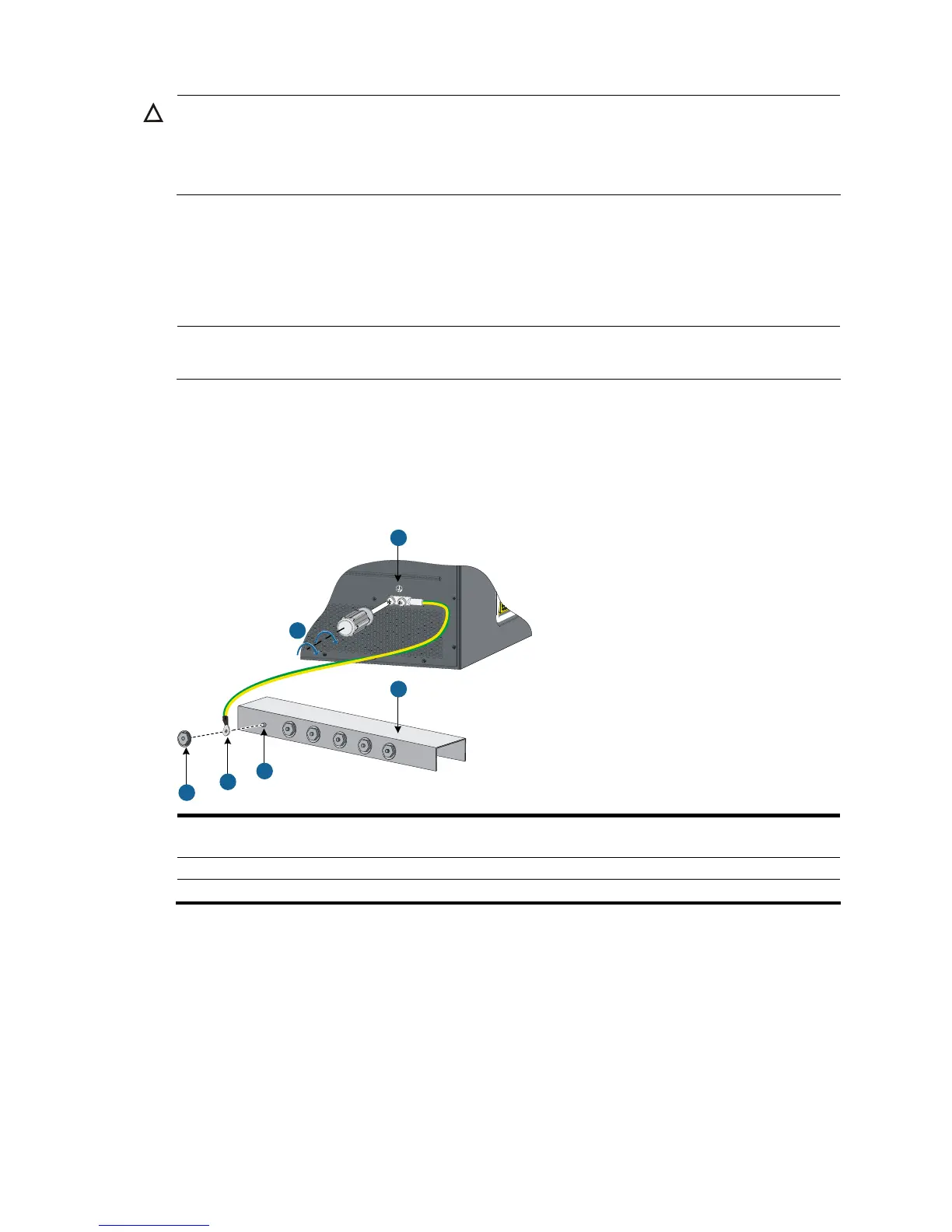
Figure 18 Connect the PGND cable to a grounding strip
1
2
3
4
5
6
1: Fix the grounding screws with dual-hole OT
terminals to the grounding holes
2: Grounding holes
3: Grounding strip 4: Grounding post
5: OT terminal 6: Hex nut
Grounding the switch through the PE wire of an AC power
supply
If the switch is AC powered and no grounding strip is available at the installation site, you can ground
the switch through the PE wire of the AC power supply, as shown in Figure 19.

 Loading...


