51
For more information about installing transceiver modules, see Chapter 4 “Installing modules.” For more
information about connecting fibers, see Chapter 6 “Connecting your switch to the network.”
CAUTION:
• The transceiver modules at the two ends of an IRF link must be the same type.
• When connectin
XFP or SFP+ ports, connect the transmit port at one end to the receive port at the other
end.
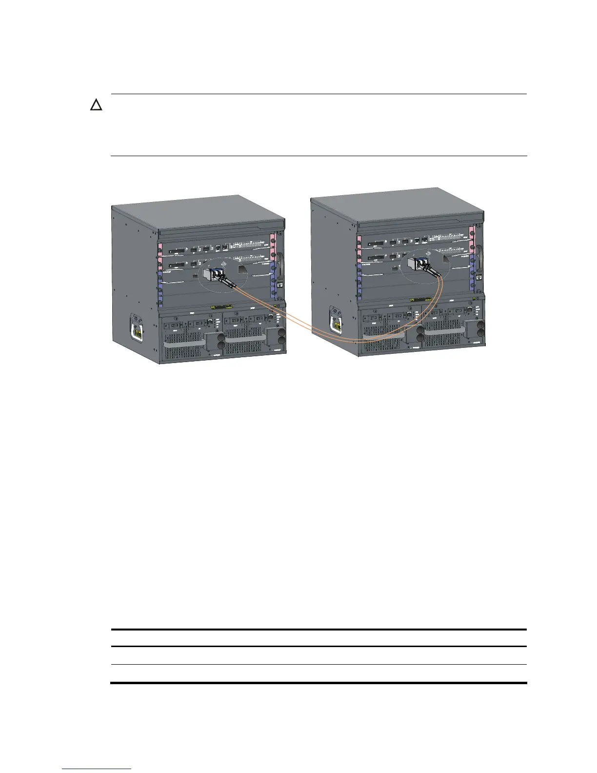
Figure 39 Connect two IRF member switches
Accessing the IRF virtual device to verify the
configuration
When you are finished configuring basic IRF settings and connecting IRF ports, follow these steps to
verify the basic functionality of the IRF virtual device:
Step1 Log in to the IRF virtual device through the console port of any member switch.
Step2 Create a Layer 3 interface, assign it an IP address, and make sure that the IRF virtual device and the
remote network management station can reach each other.
Step3 Use Telnet or SNMP to access the IRF virtual device from the network management station. (See the H3C
S7500E Series Ethernet Switches Fundamentals Configuration Guides.)
Step4 Check that you can manage all member switches as if they were one node.
Step5 Display the running status of the IRF virtual device by using the commands in Table 12. See Chapter 7
“Hardware management and maintenance.”
Table 12 Display and maintain IRF configuration and running status
To do … Use the command…
Display information about the IRF virtual device display irf
Display topology information about the IRF virtual device display irf topology

 Loading...


