149
Appendix D Cables
This chapter describes the cables used in connecting ports on different switching and routing processing
units (SRPUs) and line processing units (LPUs) of the S7500E series switches.
Table 77 Cable description
Cable Port type Application
Ethernet twisted pair cable
RJ-45 Ethernet
interfaces
Connects RJ-45 Ethernet interfaces to transmit data
Optical fiber
XFP/SFP+/SFP/EPON
interfaces
Connects the optical interfaces to transmit data
SFP+ cable SFP+ interfaces Connects SFP+ interfaces to transmit data
Ethernet twisted pair cable
An Ethernet twisted pair cable consists of four pairs of insulated wires twisted together. It mainly transmits
analog signals and is advantageous in transmitting data over shorter distances. The maximum
transmission distance is 100 m (328.08 ft).
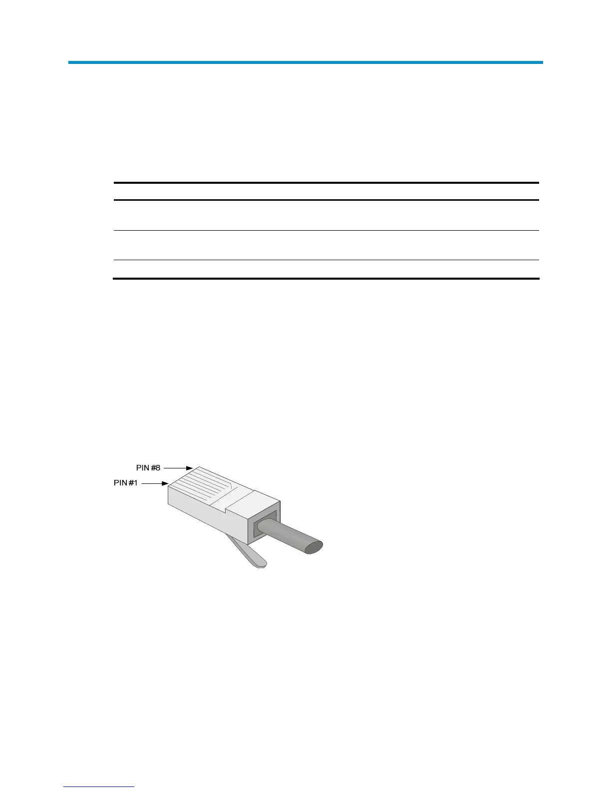
RJ-45 connector
An Ethernet twisted pair cable connects network devices through the RJ-45 connectors at the two ends.
Figure 61 show
s the pinouts of an RJ-45 connector.
Figure 61 RJ-45 connector pinout diagram
Cable pinouts
EIA/TIA cabling specifications define two standards: 568A and 568B for cable pinouts.
• Standard 568A: pin 1: white/green stripe, pin 2: green solid, pin 3: white/orange stripe, pin 4:
blue solid, pin 5: white/blue stripe, pin 6: orange solid, pin 7: white/brown stripe, pin 8: brown
solid.
• Standard 568B: pin 1: white/orange stripe, pin 2: orange solid, pin 3: white/green stripe, pin 4:
blue solid, pin 5: white/blue stripe, pin 6: green solid, pin 7: white/brown stripe, pin 8: brown
solid.

 Loading...


