31
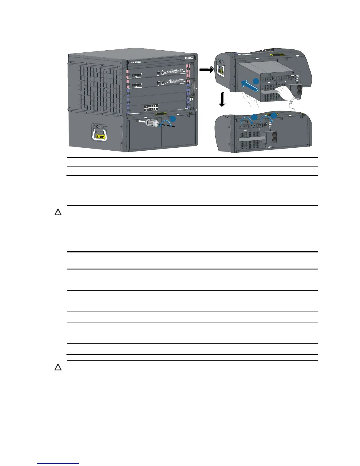
Figure 23 Install a power module
1
2
3
3
1: Remove the blank filler 2: Push the power module along the guide rails into the slot
3: Fasten the captive screws
Connecting the power cable
WARNING!
Before connectin
the power cable, make sure that the power module that connects to the power cable is
switched off.
Table 9 Power cable connection for the S7500E series
Model
Power input
(AC/DC)
PoE support Description
PSR320-A AC No Connecting the PSR320-A/PSR650-A
PSR650-A AC No Connecting the PSR320-A/PSR650-A
PSR1400-A AC No Connecting the PSR1400-A power cable
PSR2800-ACV AC Yes Connecting the PSR2800-ACV power cable
PSR6000-ACV AC Yes Connecting the PSR6000-ACV power cable
PSR320-D DC No Connecting the PSR320-D/PSR650-D power cable
PSR650-D DC No Connecting the PSR320-D/PSR650-D power cable
PSR1400-D DC Yes Connecting the PSR1400-D power cable
CAUTION:
Typically 10 A busbars are available in the equipment room but the PSR1400-A, PSR2800-ACV, and
PSR6000-ACV power modules require a 16 A power cable (AC), so you need to use a 16 A busbar,
and
ensure that the AC power supply system can provide enough power. For the power cables used in differen
countries or regions, see the chapter “Pluggable module ordering guide.”
Connecting the PSR320-A/PSR650-A
Follow these steps to connect the PSR320-A/PSR650-A:

 Loading...


