45
NOTE:
For more information about RPS800-A, see the
RPS800-A User Manual
.
Connecting a user-supplied power cable to the PoE input on the chassis rear panel
Follow these steps to connect a user-supplied power cable to the PoE input on the chassis rear panel:
Step1 Remove the blank panel covering the PoE port of the switch.
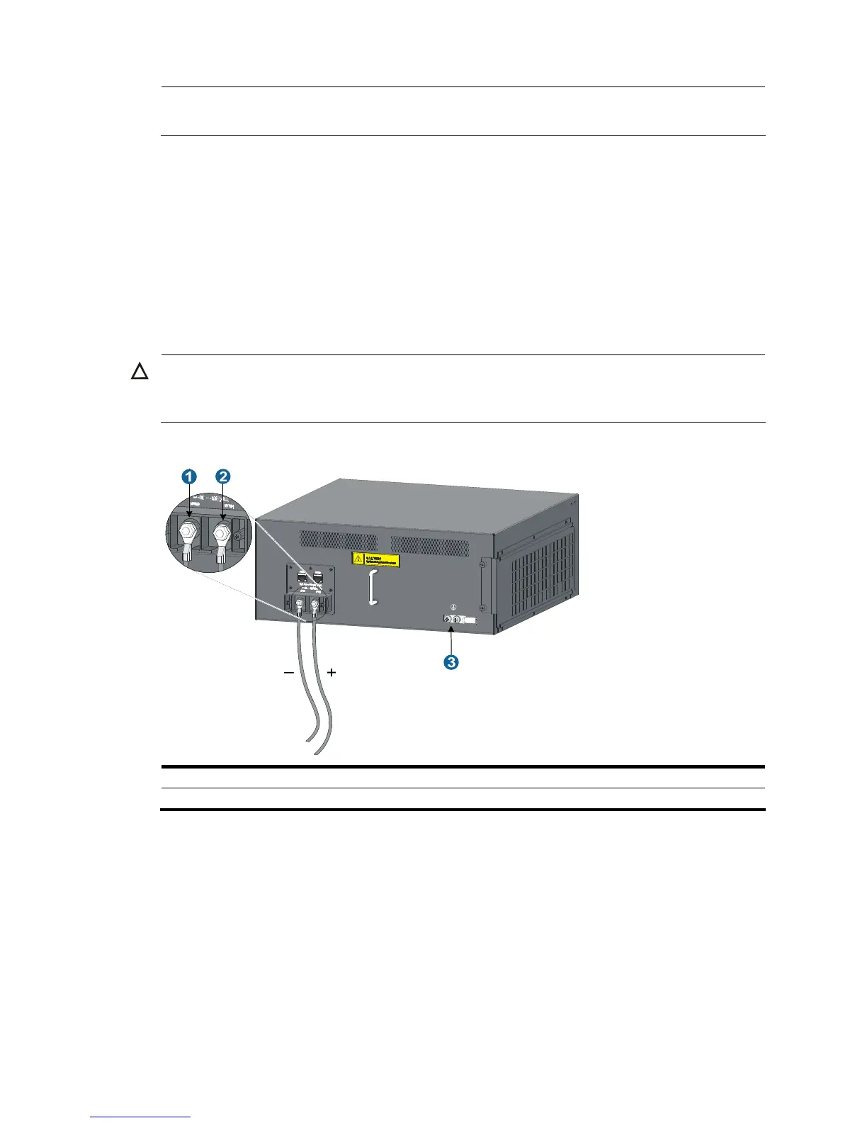
Step2 Connect the negative OT terminal on the PoE power cable to the NEG(–) terminal on the PoE power
supply socket, and fasten the captive screw. Connect the positive OT terminal on the PoE power cable to
the RTN(+) terminal on the PoE power supply socket, and fasten the captive screw.
Step3 Install the blank panel to the PoE port.
Step4 Connect the PoE power cable to the external PoE power supply.
CAUTION:
To avoid damage to the switch, be sure to connect the negative terminals to negative terminals and
positive terminals to positive terminals.
Figure 35 Connect a user-supplied power cable
1: NEG(-) terminal 2: RTN(+) terminal
3: Grounding point
Installing a CF card to the SRPU (optional)
If you select an SRPU supporting CF card, you can install a CF card as needed.
Follow these steps to install a CF card:
Step1 Push the CF card eject button all the way into the slot, and make sure that the button does not project from
the panel.
Step2 Push the CF card all the way into the CF card slot, so that it does not automatically project, as shown in
callout 4 of Figure 36. At
the same time, the eject button projects.

 Loading...


