in at the same time depends
on the number of switching and routing processing units (SRPUs), and is two on an S7500E switch
installed with two SRPUs.
• After the switches form an IRF virtual device, the maximum number of AUX users allowed to lo
in to the
IRF virtual device is the total number of SRPUs on these IRF member switches.
• The maximum number of VTY users allowed to log in at the same time is 16 for an S7500E switch of
release 6600 or later, and 5 for an S7500E switch of an earlier release.
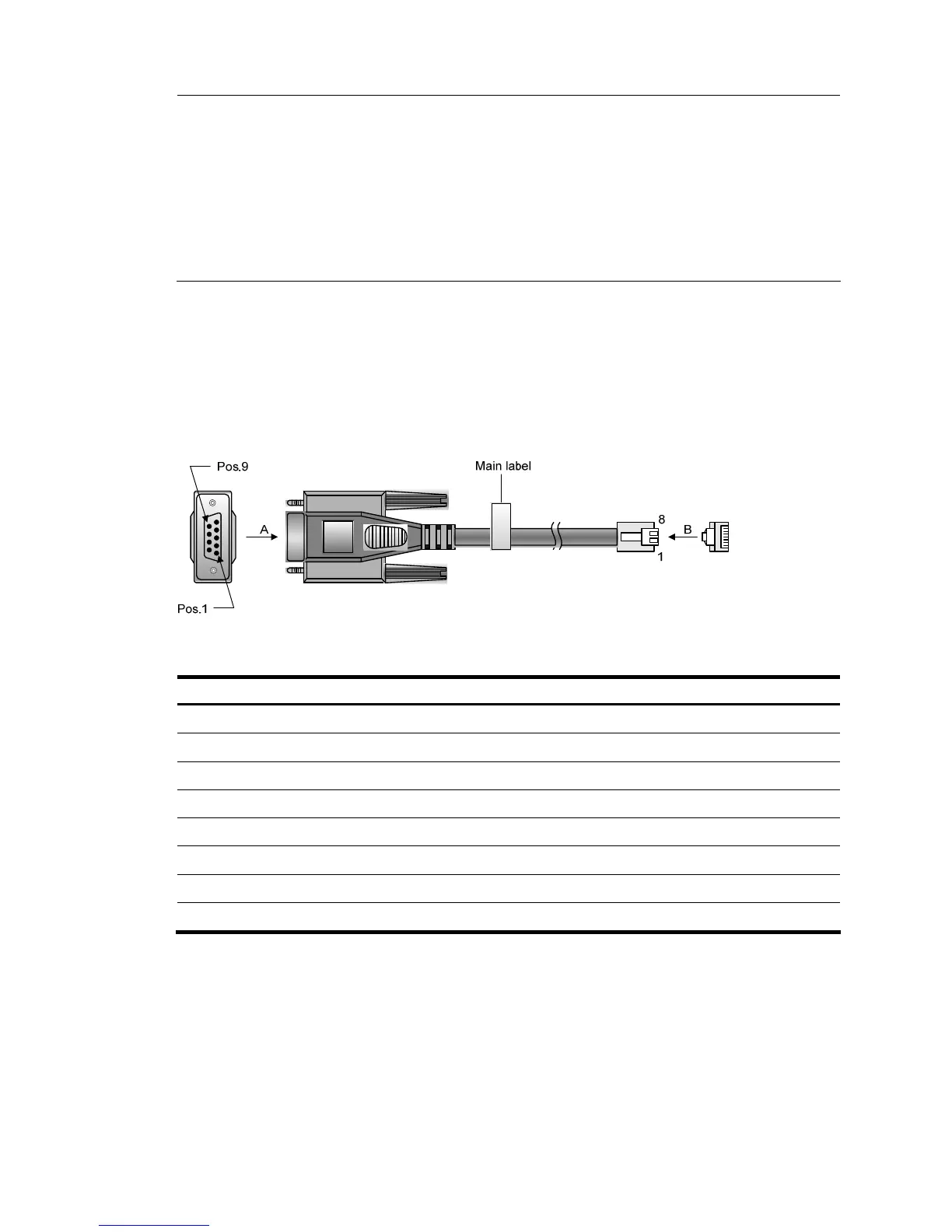
Console cable
The console cable is an 8-core shielded cable. The RJ-45 connector at one end of the cable is for the
console port of the switch, and the DB-9 female connector at the other end is for the serial port on a
configuration terminal, as shown in Figure 40.
Figure 40 Console cable
Table 14 Console cable pinouts
RJ-45 Signal DB-9 Signal
1 RTS 8 CTS
2 DTR 6 DSR
3 TXD 2 RXD
4 SG 5 SG
5 SG 5 SG
6 RXD 3 TXD
7 DSR 4 DTR
8 CTS 7 RTS
Logging in to the switch for the first time
When you log in to the switch for the first time, you can only log in through the console port.
Login prerequisites
Before logging in to the switch for the first time, make the following preparations.

 Loading...


