the master DIMM into the master DIMM slot (there is a master silkscreen on the PCB under the slot),
and the subordinate DIMM into the subordinate DIMM slot (there is a subordinate silkscreen on the PCB
under the slot).
• The master and subordinate DIMMs must be used simultaneously. The PoE system works properly only
when both of them are inserted in the correct slots.
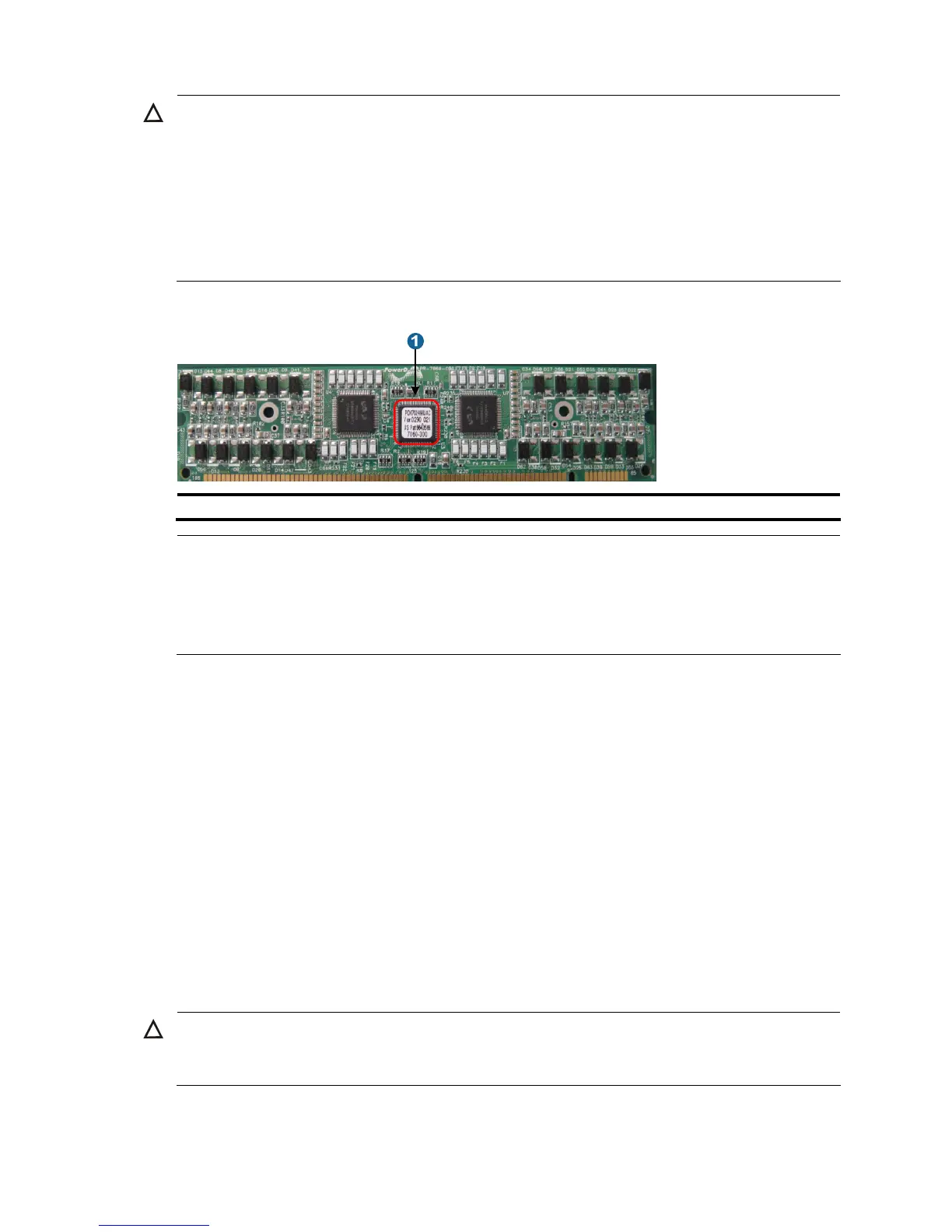
Figure 33 PoE master/subordinate DIMM
1: A chip is on the master DIMM, but not on the subordinate DIMM.
NOTE:
• If no PoE DIMM is in place or the module is not fully seated, the interface card cannot supply power,
though other functions work well.
• The PoE DIMM slot is a reverse insertion prevention slot to help you identify the direction for installin
a
PoE DIMM.
Follow these steps to install a PoE DIMM:
Step1 Wear an ESD-preventive wrist strap and make sure it has a good skin contact and is well grounded. For
more information, see “Attaching an ESD-preventive wrist strap.”
Step2 Make sure the card is sturdy. Then find the PoE DIMM slot (there is a master silkscreen on the PCB under
the slot) on the PCB.
Step3 Pull the white clips on the two sides of the PoE DIMM slot outward, as shown in callout 1 on Figure 32.
Step4 Take out the master PoE DIMM from its package, and align the golden finger of the PoE DIMM with the
groove on the slot.
Step5 As shown in Figure 32, use your thumbs to press the edges of the master PoE DIMM and push it along
the guide rail into the slot until the white clips click into the grooves on the two sides of the PoE DIMM.
Step6 Check whether the clips lock the master PoE DIMM.
Step7 Repeat steps 3 through 6 to install the subordinate DIMM to the subordinate DIMM slot (there is a
subordinate DIMM silkscreen on the PCB under the slot).
CAUTION:
Avoid touching the components on the PoE DIMM and PCB during installation and removal of a PoE
DIMM.

 Loading...


