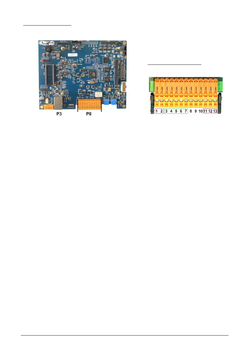
Main board
Figure 4 Main board
Figure 5 Connector P8
Connector P8
The numbers listed below refer to the 13 available P8 connections (from left to right) in Figure 5.
1. RS-485 (signal A)
2. RS-485 (signal B)
3. PROFIBUS-DP (GND)
4. PROFIBUS-DP (+ 5 V)
5. PROFIBUS-DP (signal -)
6. PROFIBUS-DP (signal +)
7. PROFIBUS-DP (signal RTS)
8. Not used
9. Not used
10. Not used
11. System alarm relay (N.O.)
12. System alarm relay (N.C.)
13. System alarm relay (Common)
Connector P3
Ethernet RJ 45. Connect the instrument to the local network by passing an ethernet cable through
the ethernet cable gland (gland location illustrated in Figure 1 on page 8) and connecting to the
P3 connector illustrated in Figure 4.
English
11
 Loading...