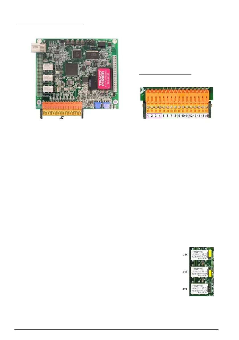
Measurement board
Figure 6 Measurement board
Figure 7 Connector J7
Connector J7 (inputs & outputs)
The numbers listed below refer to the 16 available J7 connections (from left to right) in Figure 7.
Measurement alarms relays:
1. Common
2. Output relay 1
3. Output relay 2
4. Output relay 3
Analog current
outputs:
5. Analog GND
6. Output 1
7. Output 2
8. Output 3
Digital inputs:
9. Hold input. To deactivate the sensor from a PLC system, connect a dry contact
between J7.9 and J7.12
Note: It is recommended to use this functionality in order to extend the sensor lifetime for
installations with a CIP process that can damage the spot.
10. to 11. Not used
12. Digital GND
13. to 16. Not used
Measurement alarm relays
The three output relays are located on the measurement board.
They can be individually configured to Normally Open (NO) or to Normally Closed (NC) by
physically moving the jumper on each relay. On the illustration:
• Upper relay is set to NC
• Middle relay is set to NO
• Lower relay is shown with no jumper
Note: J14 is relay 1, J18 is relay 2, J19 is relay 3
12 English
 Loading...