Appendix A Legacy Hardware Platforms
© 2017 Harmonic Inc. All rights reserved. 300 Harmonic MediaGrid Release 4.1
ContentDirector 1000B/1000C/1000D and High Performance ContentDirector 2000
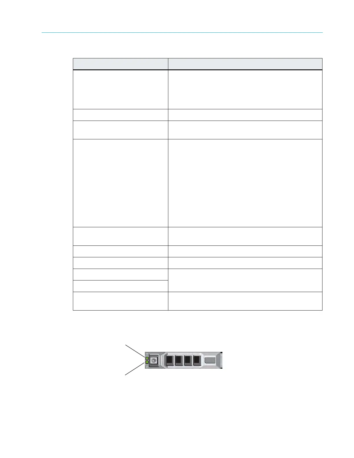
Table A–3: ContentDirector Front Panel Components
Figure A–4 and Ta
ble A–4 describe the typical hard drive indicators and their functions.
Figure A–4: ContentDirector Hard Drive Indicators
Indicator, Button, or Connector Description
1. Power-on indicator/button The power button controls the DC power supply output
to the sys
tem.
The power-on indicator lights when the system power is
on. Wh
en the power-on indicator is off, this indicates that
no power is supplied to the system.
2. Video Connector Connects a monitor to the system.
3. LCD menu buttons Allows you to navigate the control panel
LCD menu.
4. LCD display Provides status information and system error messages.
The LCD display lights during normal system operation.
B
o
th the systems management software and the
identification buttons located on the front and back of the
system can cause the LCD to flash blue to identify a
particular system.
The LCD display lights amber when the system needs
attention d
u
e to a problem with power supplies, fans,
system temperature or hard drives.
Note: If
the system is connected to AC power and an
err
or has been detected, the LCD display lights amber
regardless of whether the system has been powered on.
5. System identification button Pressing this button will cause the Fr
ont LCD display and
the system status indicator on the rear panel to blink.
6. USB connectors Use to connect the front bezel.
7. Optical drive Use for software installation.
8. Hard drive 0 Refer to Table A–4 for a description of the indicator codes.
9. Hard drive 1
10. Solid state drive Available only in the High Performance ContentDirector
2000.
Drive-activity Indicator (green)
Drive-status Indicator (green and amber)