Appendix A Legacy Hardware Platforms
© 2017 Harmonic Inc. All rights reserved. 301 Harmonic MediaGrid Release 4.1
ContentDirector 1000B/1000C/1000D and High Performance ContentDirector 2000
Table A–4: Drive-status Indicator Pattern (RAID Only)
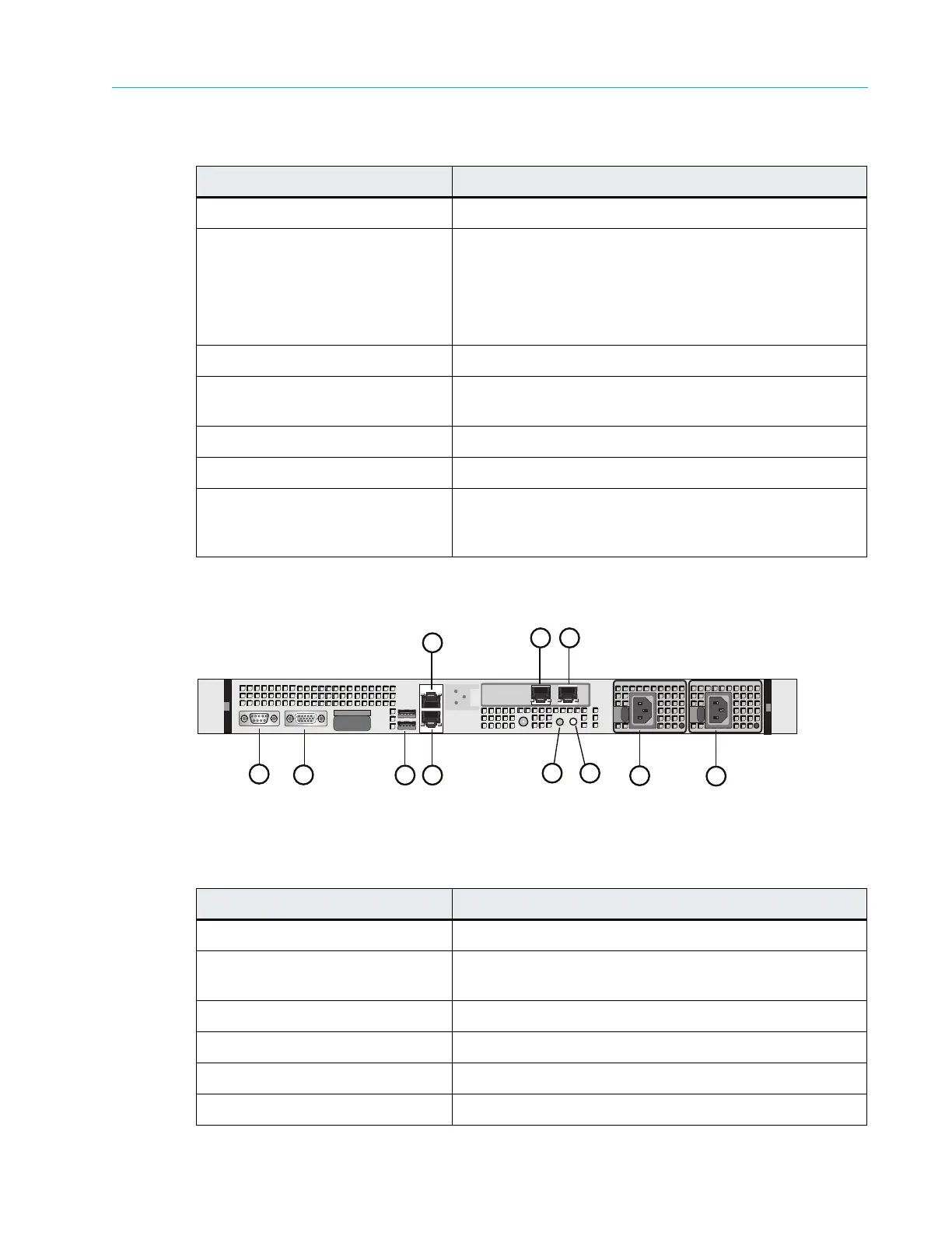
Figure A–5 and Ta
ble A–5 describe the rear panel view of the ContentDirector.
Figure A–5: Rear View of ContentDirector
Table A–5: ContenDirector Rear Panel Components
Drive-status Indicator Pattern Condition
Blinks green two times per second Identify drive/preparing for removal
Off Drive ready for insertion or removal
Note: The drive-status indicator remains off
until all hard drives are initialized after system
power is applied. Drives are not ready for
insertion or removal during this time.
Blinks green, amber, and off Drive predicted failure
Blinks amber four times per
second
Drive failed
Blinks green slowly Drive rebuilding
Steady green Drive online
Blinks green three seconds,
amber thr
ee seconds, and off six
seconds
Rebuild aborted
Indicator, Button, or Connector Description
1. Serial connector Use to connect a serial device to the system
2. Video connector Use to connect a monitor to the system (for maintenance
only).
3. USB connectors (2) Used for maintenance purposes only.
4. NIC 0 connector Use for Gigabit Ethernet connection to switch.
5. NIC 1 connector Use for Gigabit Ethernet connection to switch.
6. NIC 2 connector Use for Gigabit Ethernet connection to switch.
3
1
2
5
4
8 9
6
7
10
11