GigE Area Scan Camera User Manual
7
Device’s power supply ground
Device’s power supply ground
Table 3-2 Pin Definitions of 6-Pin P7 Connector (Other Series)
Can be configured as input or
output
Opto-isolated signal ground
Device’s power supply ground
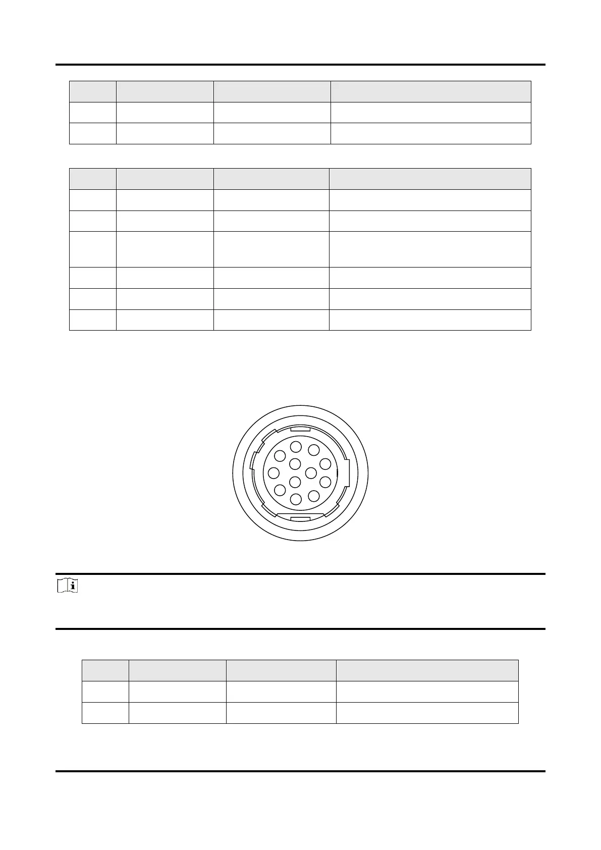
12-Pin P10 Connector
The 12-pin P10 connector is applicable to type V, type VI, type VII, and type VIII devices.
The pin definitions are shown below.
Figure 3-2 12-Pin P10 Connector
Note
Refer to the table below and the label attached to the power and I/O cable to wire the
device.
Table 3-3 Pin Definitions of 12-Pin P10 Connector
Device’s power supply ground