GigE Area Scan Camera User Manual
40
Chapter 10 I/O Electrical Features and Wiring
10.1 I/O Electrical Features
10.1.1 Electrical Features of Opto-Isolation
Apart from CU series devices, the Line 0 in I/O signal of other series devices is
opto-isolated input, and Line 1 in I/O signal of other series devices is opto-isolated output.
Input Signal
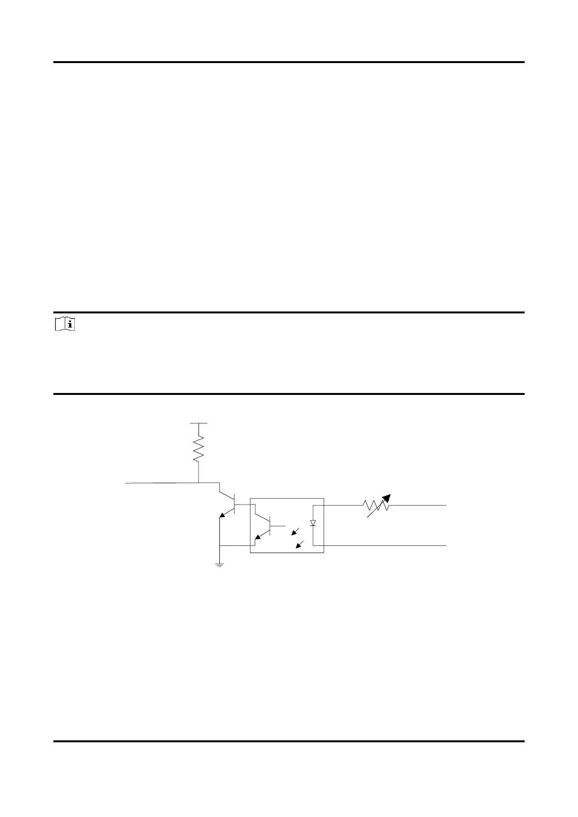
The internal circuit of opto-isolated input (Line 0) is as follows.
Note
●
The maximum input current of Line 0 is 25 mA.
●
Make sure that the input voltage is not from 1 VDC to 3.3 VDC as the electric status
between these two values are not stable.
●
The breakdown voltage is 30 VDC. Keep voltage stable.
 Loading...

