EasyManua.ls Logo

HikRobot GigE - I;O Wiring

HikRobot GigE
130 pages
Print Icon
To Next Page IconTo Next Page
To Previous Page IconTo Previous Page
Loading...
GigE Area Scan Camera User Manual
45
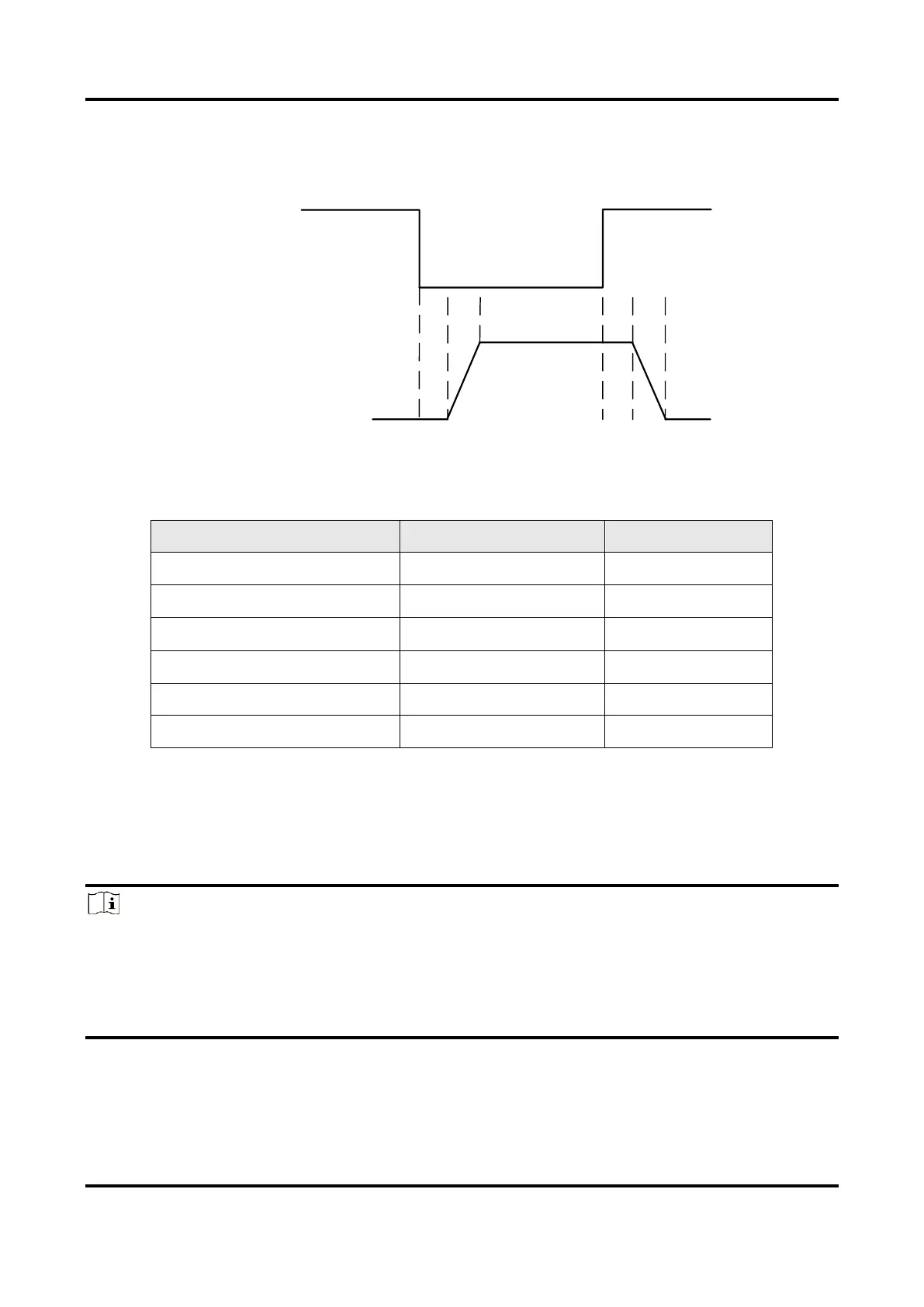
When the voltage of external resistance (1 ) is pulled up to 5 VDC, the logic level and
electrical features of configuring Line 2 to output are shown below.
Logic 1
Output Level
Logic 0
Output Level
Internal
Logic
TDR TDF TFTR
Figure 10-8 Output Logic Level
Table 10-6 Output Electrical Feature
Parameter Name
Parameter Symbol
Value
Output Logic Level Low
VL
220 mV
Output Logic Level High
VH
4.75 VDC
Output Rising Time
TR
0.06 μs
Output Falling Time
TF
0.016 μs
Output Rising Delay
TDR
0 μs to 4 μs
Output Falling Delay
TDF
< 1 μs
10.2 I/O Wiring
This section introduces the I/O wiring of the devices, including opto-isolated wiring and
non-isolated wiring.
Note
I/O wiring may differ by the external device type.
Here we take type V device as an example to introduce opto-isolated wiring, and the
appearance here is for reference only.
Here we take type I device as an example to introduce non-isolated wiring, and the
appearance here is for reference only.

Table of Contents

Related product manuals