GigE Area Scan Camera User Manual
6
Chapter 3 I/O Connector and Indicator
3.1 Power and I/O Connector
The device has a 6-pin P7 connector or 12-pin P10 connector as the power and I/O
connector that provides power supply, input/output signal and serial port function.
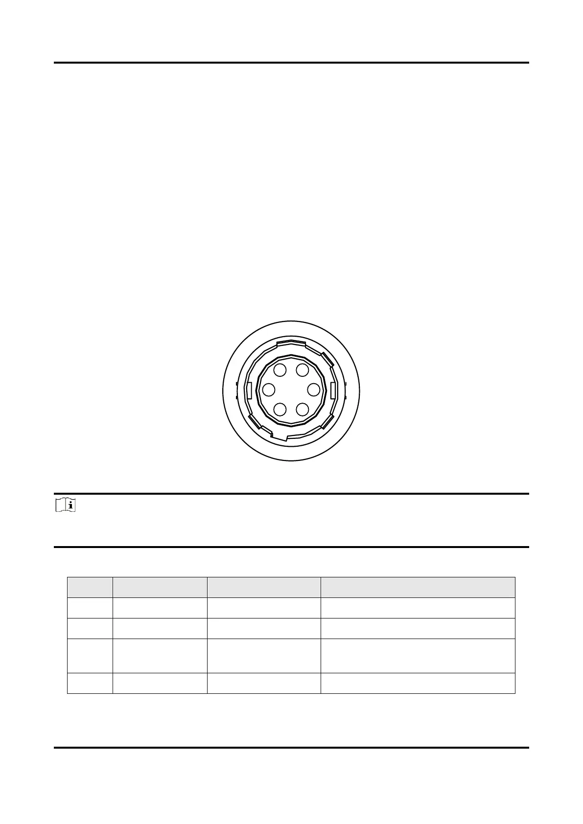
6-Pin P7 Connector
The 6-pin P7 connector is applicable to type I, type II, type III, and type IV devices. However,
the pin definitions of various device series are different. The pin definitions of CU series
(type III device) are shown in Table 3-1 and pin definitions of other series devices are
shown in Table 3-2.
Figure 3-1 6-Pin P7 Connector
Note
Refer to the table below and the label attached to the power and I/O cable to wire the
device.
Table 3-1 Pin Definitions of 6-Pin P7 Connector (CU Series)