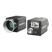
Figure 10-13 Output Signal Connects to NPN Device
10.2.2 Non-Isolated Wiring
Input Signal
The Line 2 of all series devices are non-isolated bi-directional I/O that can be configured to
input signal.
Note
●
The input signal wiring may differ by the external device type.
●
The Line 0 of CU series devices is non-isolated input, and its wiring can refer to figures
below.
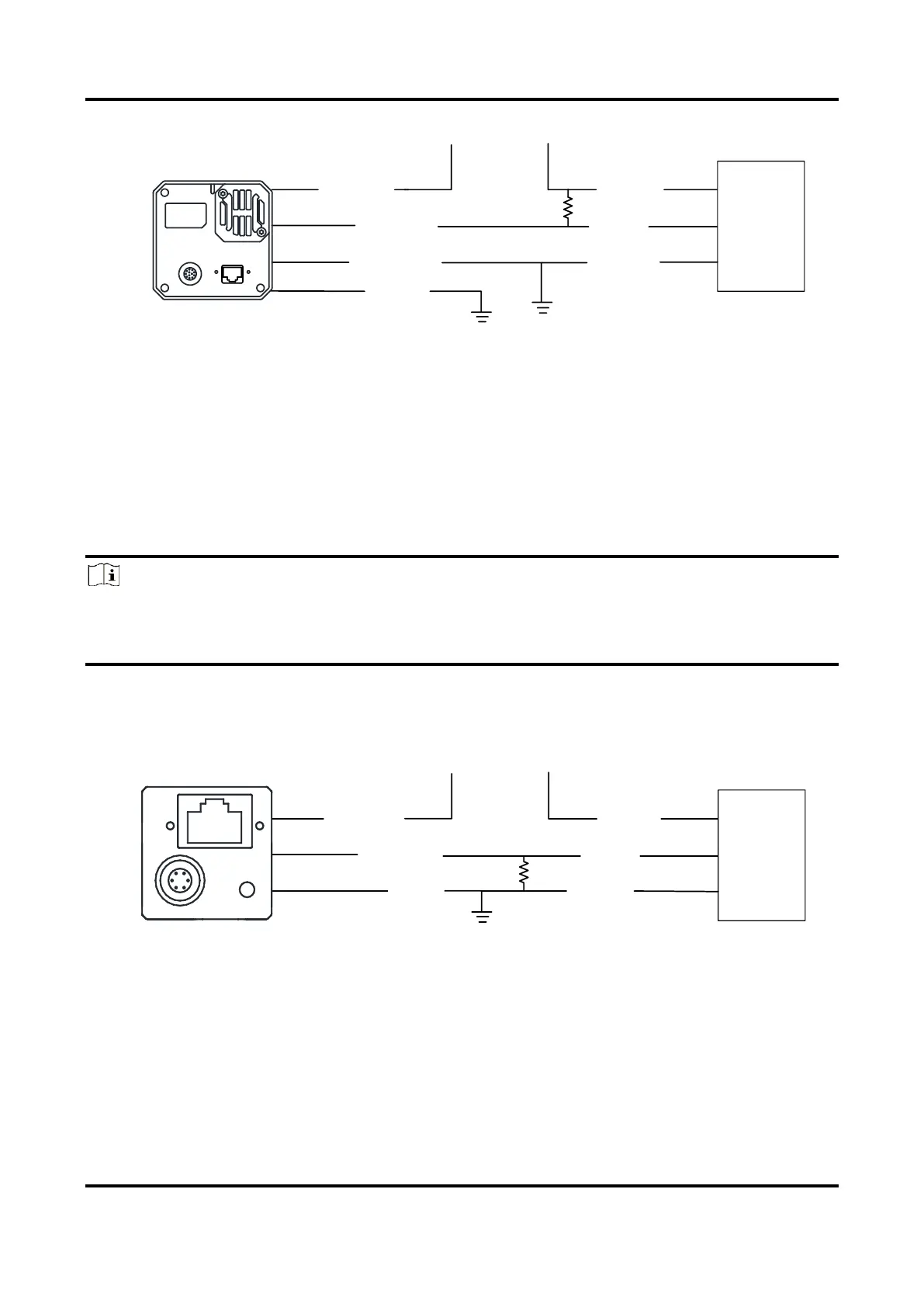
PNP Device
It is recommended to use 330 Ω pull-down resistor.
Figure 10-14 Input Signal Connects to PNP Device
NPN Device
●
If the VCC of NPN device is 24 VDC, it is recommended to use 4.7 KΩ pull-up resistor.
●
If the VCC of NPN device is 12 VDC, it is recommended to use 1 KΩ pull-up resistor.