EasyManua.ls Logo

HikRobot GigE - Page 60

HikRobot GigE
130 pages
Print Icon
To Next Page IconTo Next Page
To Previous Page IconTo Previous Page
Loading...
GigE Area Scan Camera User Manual
49
Camera Power
Bi-direction I/O
Camera Power
Ground
PWR VCC
NPN Power
Signal Line
NPN Device
GND of PWR and VCC
NPN Power
Ground
●
●
●
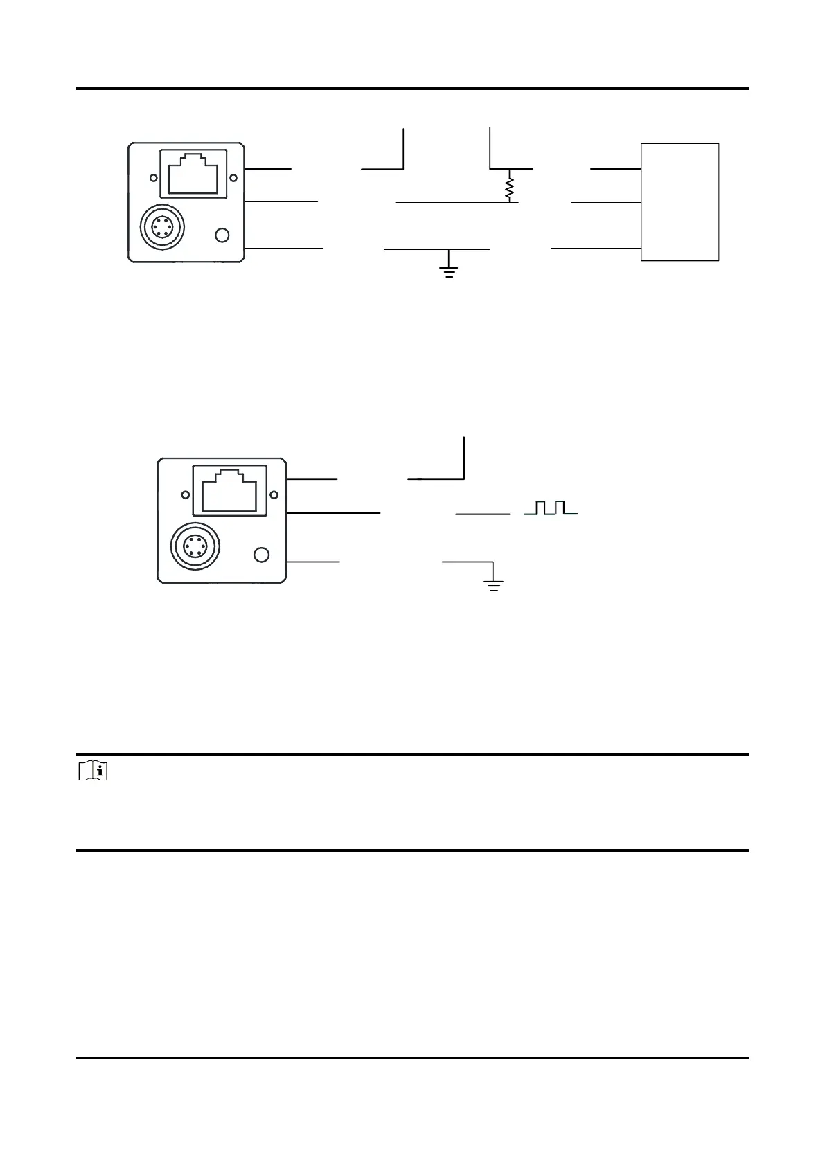
Figure 10-15 Input Signal Connects to NPN Device
Switch
The switch value can provide low electrical level to trigger Line 2.
Camera Power
PWR
Bi-direction I/O
Camera Power Ground
GND of PWR and VCC
0 V
> 3.3 V
Figure 10-16 Input Signal Connects to Switch
Output Signal
The Line 2 of all series devices are non-isolated bi-directional I/O that can be configured to
output signal.
Note
●
The output signal wiring may differ by the external device type.
●
The Line 1 of CU series devices is non-isolated output, and its wiring can refer to figures
below.

Table of Contents