EasyManua.ls Logo

HikRobot GigE - Electrical Features of Non-Isolation

HikRobot GigE
130 pages
Print Icon
To Next Page IconTo Next Page
To Previous Page IconTo Previous Page
Loading...
GigE Area Scan Camera User Manual
43
10.1.2 Electrical Features of Non-Isolation
Input Signal
The Line 0 of CU series devices is non-isolated input, and Line 2 of all series devices are
non-isolated bi-directional I/O that can be configured to input signal. The internal circuit of
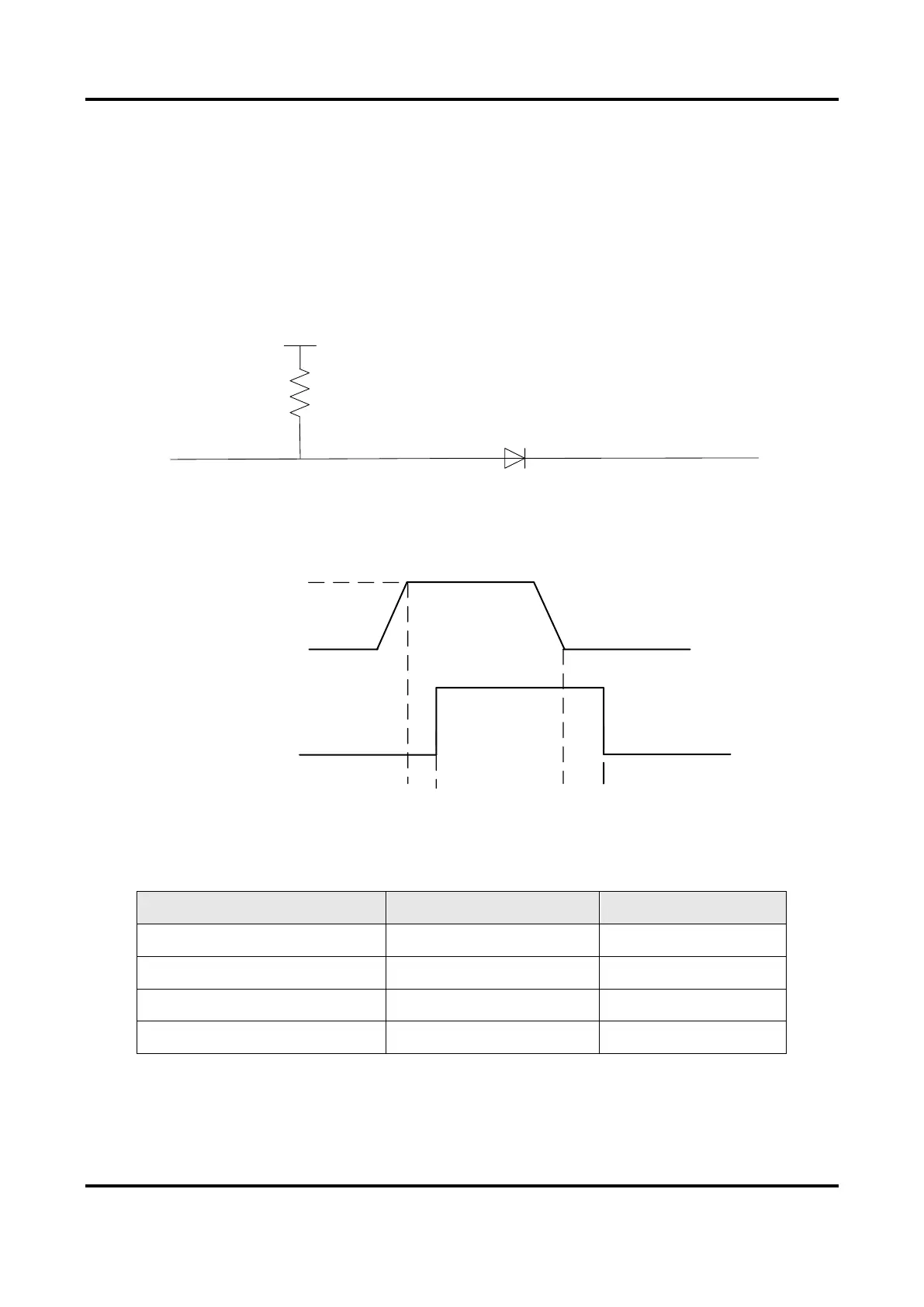
non-isolated input is shown below.
*
GPI
VCC
Figure 10-5 Internal Circuit of Non-Isolated Input
With the condition of 100 Ω resistance and 5 VDC voltage, the logic level and electrical
features of configuring Line 2 to input signal are shown below.
Logic 1
Input Level
Logic 0
Input Level
Internal Logic
TDR TDF
Figure 10-6 Input Logic Level
Table 10-4 Input Electrical Feature
Parameter Name
Parameter Symbol
Value
Input Logic Level Low
VL
0 VDC to 0.3 VDC
Input Logic Level High
VH
3.3 VDC to 24 VDC
Input Falling Delay
TDF
< 1 μs
Input Rising Delay
TDR
< 1 μs

Table of Contents

Related product manuals