GigE Area Scan Camera User Manual
44
Note
●
Make sure that the input voltage is not from 0.3 VDC to 3.3 VDC as the electric status
between these two values are not stable.
●
The breakdown voltage is 30 VDC. Keep voltage stable.
●
To prevent damage to the GPIO pin, please connect GND first and then input voltage in
non-isolated input pins.
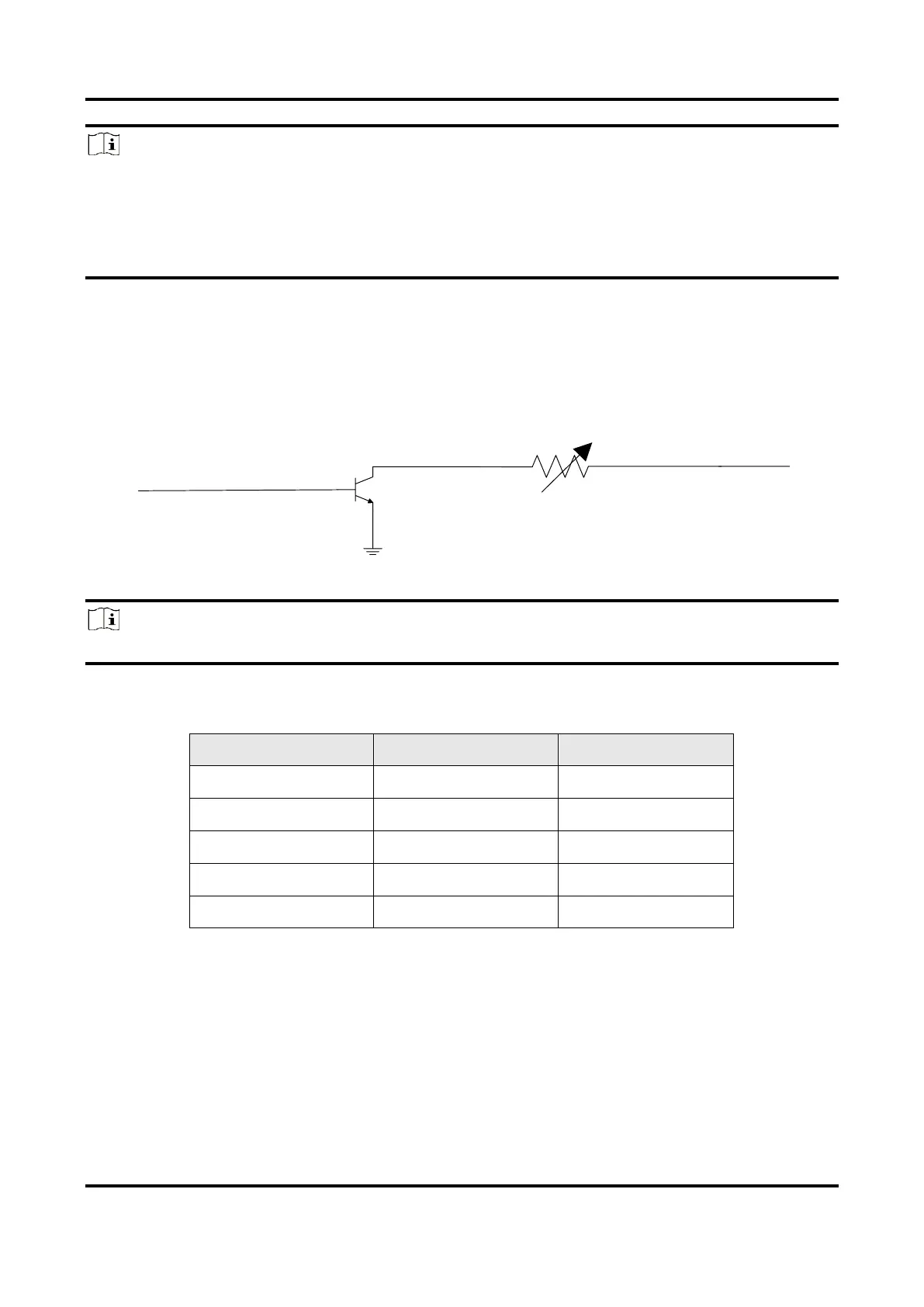
Output Signal
The Line 1 of CU series devices is non-isolated output, and Line 2 of all series devices are
non-isolated bi-directional I/O that can be configured to output signal. The internal circuit
of non-isolated output is shown below.
Figure 10-7 Internal Circuit of Non-Isolated Output
Note
The maximum current is 25 mA and the output impedance is 40 Ω.
The relation among external voltage, resistance and the output level low is shown below.
Table 10-5 Parameters of Output Logic Level Low