B 5230 / H51q-M (0605)
94
4.6 Connections on the rear
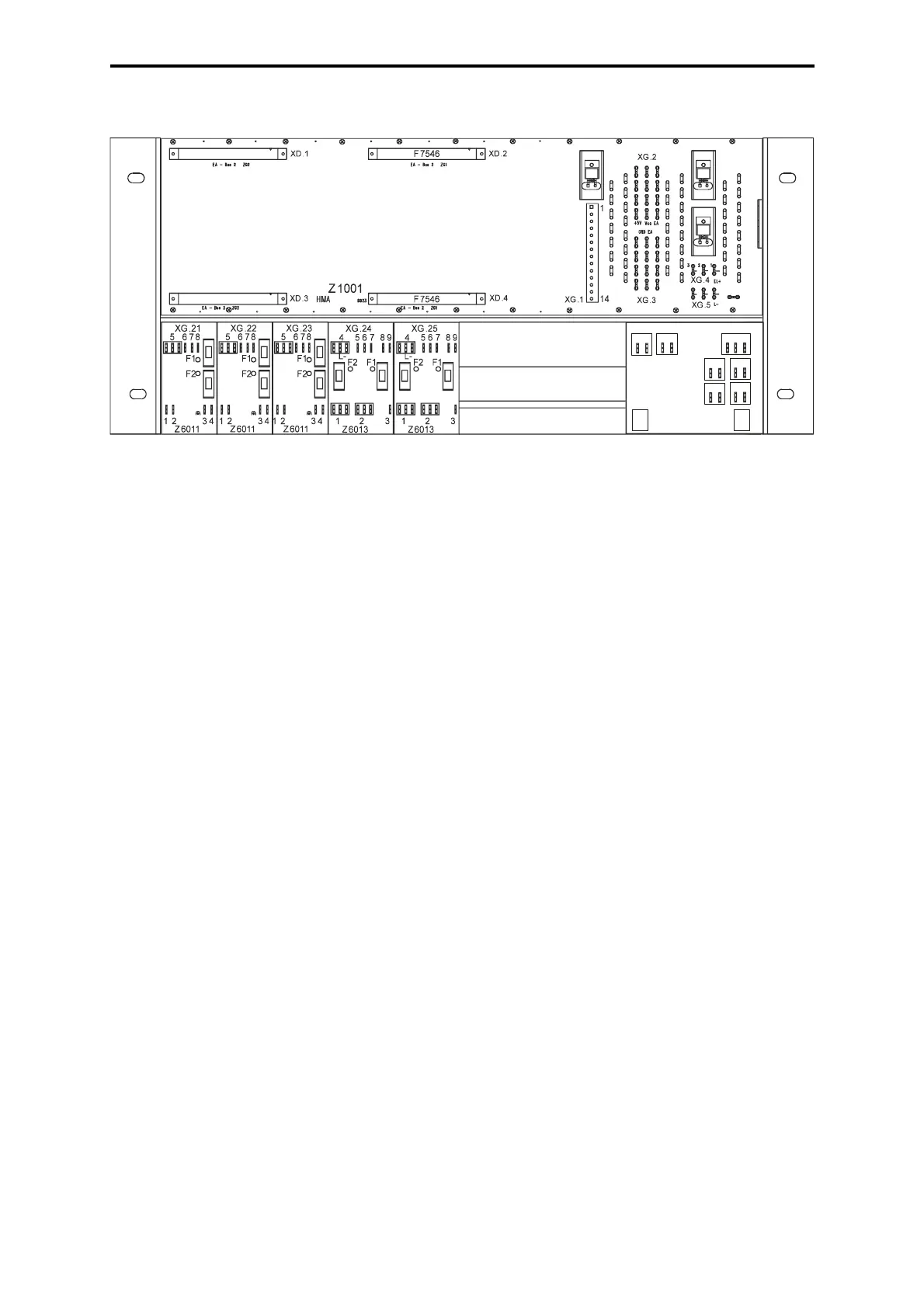
Figure 4: Connections on the rear of the system rack K 1412B
4.6.1 Wiring ex works
XD.1 Connection data cable BV 7032
(not used in single channel system H51q-M)
XD.2 Bus termination module F 7546 plugged /
Connection data cable BV 7032
XD.3 Connection data cable BV 7032
(not used in single channel system H51q-M)
XD.4 Bus termination module F 7546 plugged /
Connection data cable BV 7032
XG.1: 1, 3 Watchdog supply for module Z 6013
XG.1: 5, 7 Watchdog supply for module Z 6013
XG.1: 12 - 13 Connection external buffer battery on module F 7131
XG.1: 14 Ground (GND) for connection external buffer battery
XG.4 L+ for power supply 24V
XG.5 Reference potential: (L-)
Connections of the additional modules (see assembly kit, wiring diagram)
XG.24, XG.25 Z 6013
XG.26 Z 6018
4.6.2 Wiring by customer
XG.1: 2, 4 Watchdog signal for I/O modules
XG.1: 9 - 11 Monitoring power supply PS1 - PS3 by F 7131 for external exam-
ination
XG.2 Connection 5 VDC for I/O subrack
XG.3 Ground (GND) for supply 5 VDC
XG.21, XG.22, XG.23 Supply 24 V via module Z 6011
(see assembly kit, wiring diagram) L+, L-
Z 6018
1a 1b
2 3
7 8
9 10
11 12
13 14
4 5 6
XG.26
 Loading...