H 7014 (0507)
All rights reserved. Equipment subject to change without notice: 473
HIMA Paul Hildebrandt GmbH + Co KG, P.O. Box 1261, 68777 Brühl
H 7014
H 7014: Electronic fuses
• for the safety-related outputs of the F 3330 module
• resistive or inductive loads up to 500 mA (12 W)
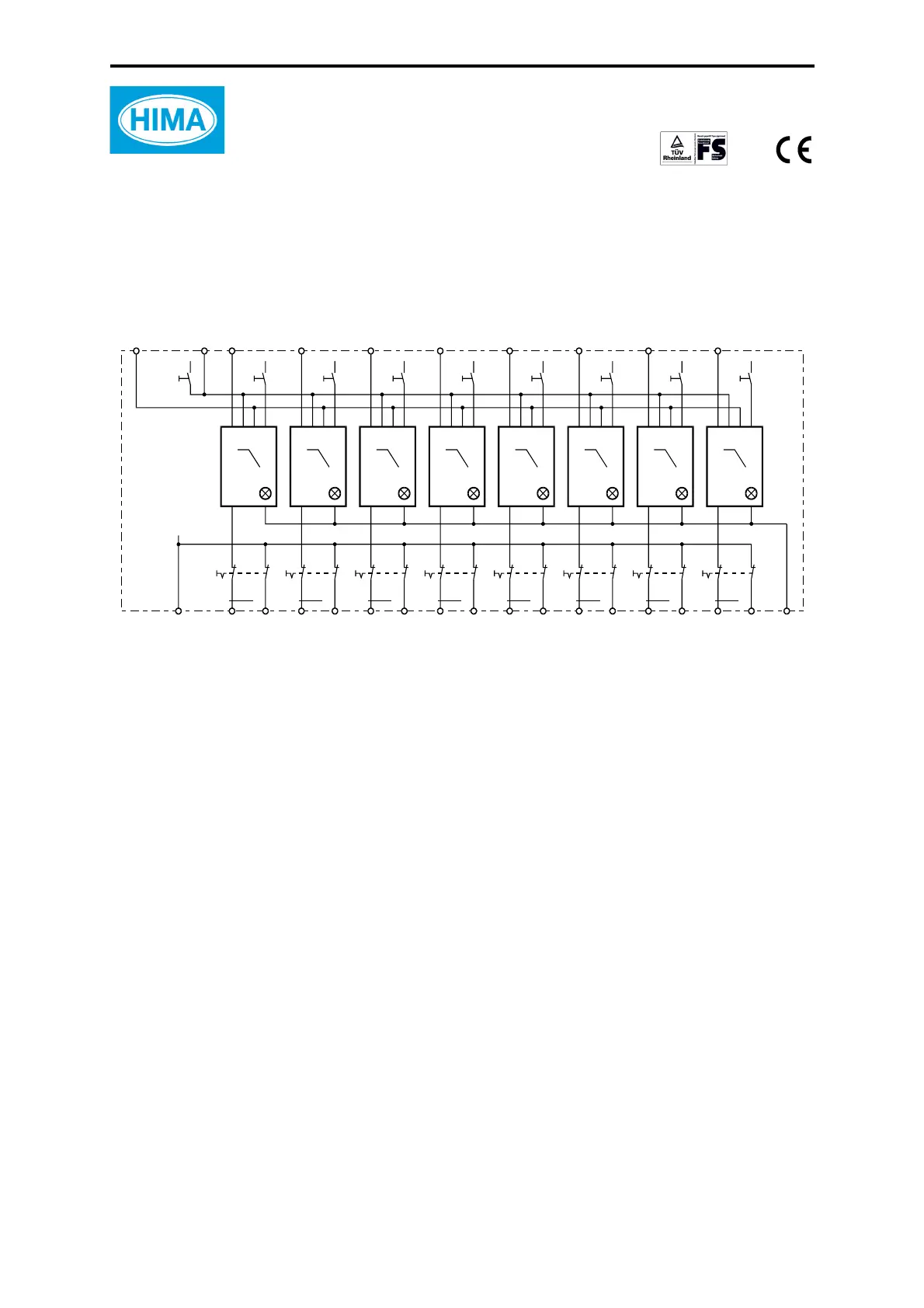
Figure 1: Block diagram
The module is tested according to IEC 61508-2 (SIL 3), IEC 61131-2,
EN 298, DIN VDE 0116, EN 50156, EN 50178 (and DIN V 19250).
The electronic fuses are dimensioned to be connected to the outputs (also redundant outputs)
of the F 3330 module.
All input signals for the H 7014 must be generated in SELV systems.
The output loads can be disconnected separately with slide switches.
Inputs voltage range matched to the outputs
of the F 3330 module
Current consumption
≤ 10 mA per channel
Load rating of the output F 1 input F 3221 or F 3236
Operating point approx. 550 mA
Switching time < 200
μs
Switching frequency
≤ 1 Hz
Ambient conditions 0...+60 °C
Degree of protection IP 20 according to IEC/EN 60529 (VDE 0470 part 1)
12 W 12 W 12 W 12 W 12 W 12 W 12 W 12 W
L-
IN L-
OUT K1
OUT K2
OUT K3
OUT K4
OUT K5
OUT K6
OUT K7
OUT K8
OUT L-
OUT L-
OUT L-
OUT L-
OUT L-
OUT L-
OUT L-
OUT L-
F
IN K1
IN K2
IN K3
IN K4
IN K5
IN K6
IN K7
IN K8
W
T
12345678
0.5A 0.5A 0.5A 0.5A 0.5A 0.5A 0.5A 0.5A
Reset
K1...K8
ON
OFF
Tes t
Reset
Tes t 1 Tes t 2 Test 3 Test 4 Test 5 Te st 6 Te st 7 Te st 8
Fault
 Loading...