H 7015A (0524)
481
Allocation of the P+F Modules to the Terminal Module H 7015A
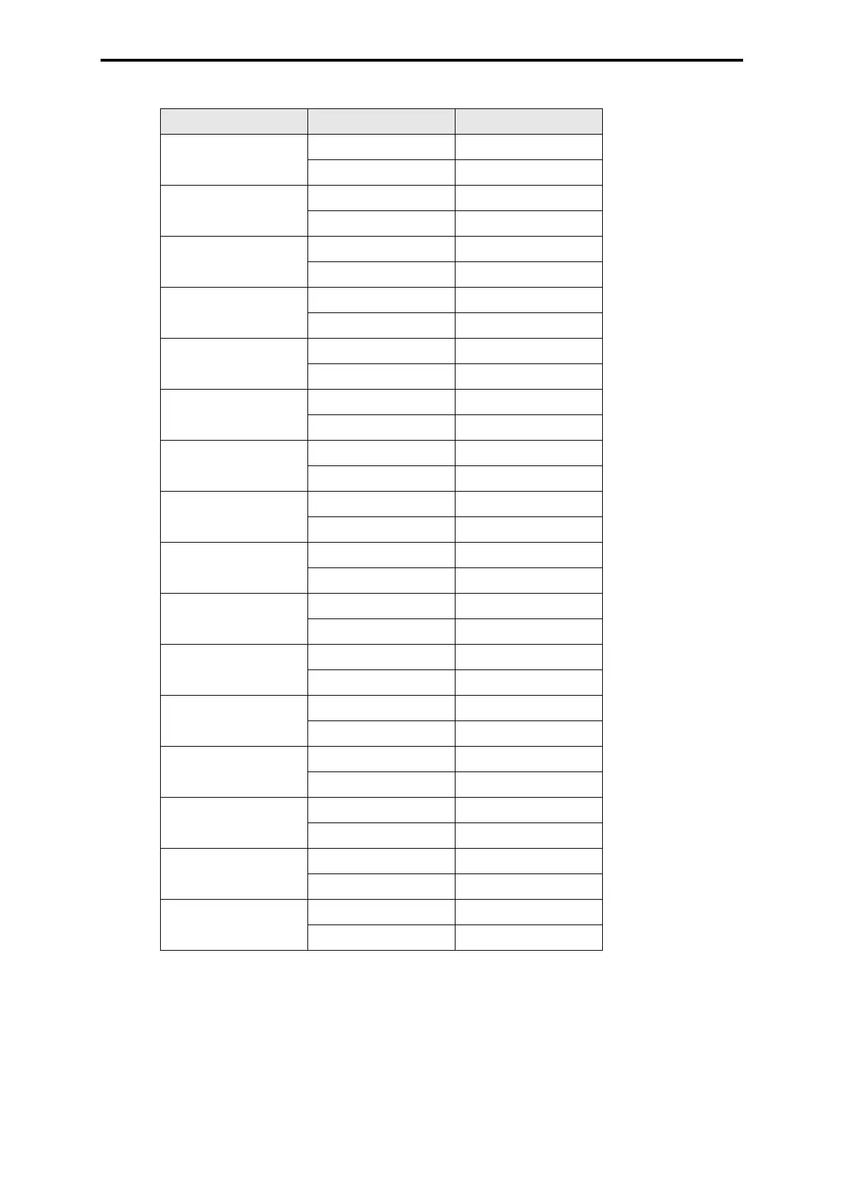
Table 4: Allocation of the P+F Modules
Motherboard Motherboard (X1) H 7015A (A,B,C)
Module 1 1 (A) A1, B1, C1
2 (B) A2, B2, C2
Module 2 3 (C) A3, B3, C3
4 (D) A4, B4, C4
Module 3 5 (E) A5, B5, C5
6 (F) A6, B6, C6
Module 4 7 (H) A7, B7, C7
8 (J) A8, B8, C8
Module 5 9 (K) A9, B9, C9
10 (L) A10, B10, C10
Module 6 11 (M) A11, B11, C11
12 (N) A12, B12, C12
Module 7 13 (P) A13, B13, C13
14 (R) A14, B14, C14
Module 8 15 (S) A15, B15, C15
16 (T) A16, B16, C16
Module 9 17 (U) A17, B17, C17
18 (V) A18, B18, C18
Module 10 19 (W) A19, B19, C19
20 (X) A20, B20, C20
Module 11 23 (a) A21, B21, C21
24 (b) A22, B22, C22
Module 12 25 (c) A23, B23, C23
26 (d) A24, B24, C24
Module 13 27 (e) A25, B25, C25
28 (f) A26, B26, C26
Module 14 29 (h) A27, B27, C27
30 (j) A28, B28, C28
Module 15 31 (k) A29, B29, C29
32 (l) A30, B30, C30
Module 16 33 (m) A31, B31, C31
34 (n) A32, B32, C32