Installation and Connections
36
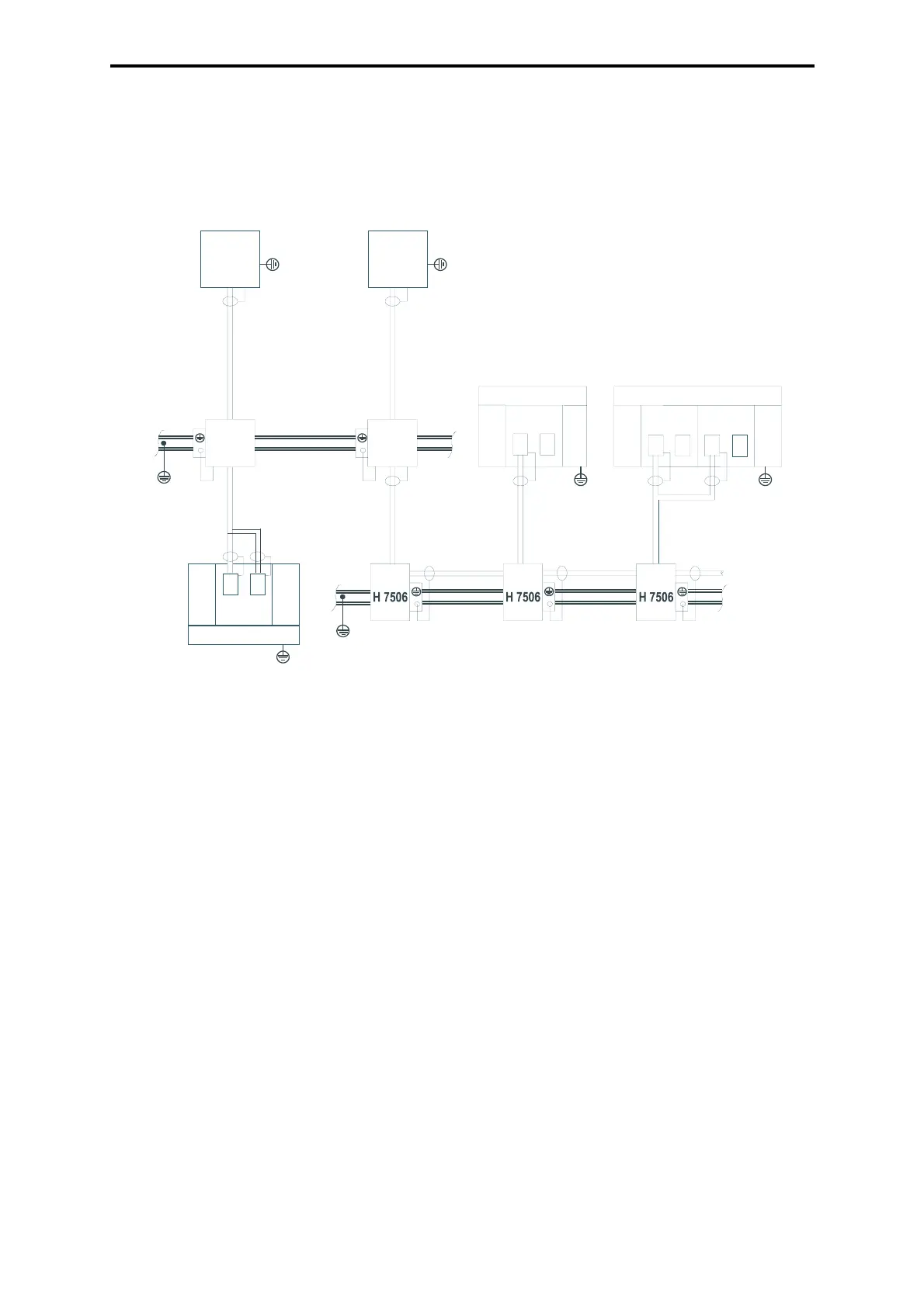
The shield of the BV 7044 cable for the connection
3
) of the H 7505 interface converter is
earthed on the PC (PADT) side.
The measures
1
),
2
),
3
) are standardized already finished in HIMA. The connections
4
),
5
),
6
)
have to be performed during the installation on site. The shielding connection using a special
cable
7
) does already exist or has to be performed depending on the special cable.
Figure 11: Connection of the cable shields
8.7 Shielding in the Input/Output Area
At installation of the field cables pay attention to the fact, that the cables to sensors and actu-
ators are separated from power supply cables and in a sufficient distance from electromagnetic
active devices (motors, transformers).
Cables to the input modules of the H41q/H51q systems have to be installed interference-free
as possible e. g. as shielded cables.
This applies especially to cables with analog signals and for proximity switches.
With cable connectors having a shield termination line this has to be connected to the bus bar
of the I/O rack below the slot of the module.
Further informations on the requirements of shielding and earthing you will find in the data
sheets of the modules.
B
7044
PC
X2/1
H 7505
H41q
51q
PLS
X2/1
H 7505
PE
PE
PE
PE
PE
H41q/51q
CU
H41q/51q
CU2
CU
CU
1
PE
PE
BV 7048 BV 7040 BV 7040
BV 7046
Pin 5
4
)
3
)
2
)
1
)
1
)
1
)
1
)
2
)
4
)
4
)
5
)
5
)
6
)
6
6
)
6
)
6
)
7
)
special cable
Top hat rail
Top hat rail
PC = PADT (Programming
and Debugging Tool)
CU = Central Module
PLS = Process Control System