F 3330 (0602)
All rights reserved. Equipment subject to change without notice: 225
HIMA Paul Hildebrandt GmbH + Co KG, P.O. Box 1261, 68777 Brühl
F 3330
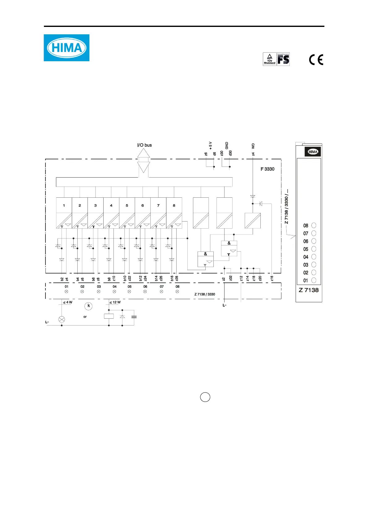
F 3330: 8-channel output module
safety-related, applicable up to SIL 3 according to IEC 61508
• resistive or inductive load up to 500 mA (12 W)
• lamp load up to 4 W
• with integrated safety shutdown, with safe isolation
• no output signal with break of the L- supply
Figure 1: Block diagram and front cable plug
The module is automatically tested during operation. The main test routines are:
– Reading back of the output signals. The operating point of the 0-signal read back is
≤ 6.5 V. Up to this value the level of the 0-signal may arise in case of a fault and this will
not be detected
– Switching capability of test signal and cross-talking (walking-bit test).
Outputs 500 mA, short-circuit-proof
Internal voltage drop max. 2 V at 500 mA load
Admissible line resistance (in + out) max. 11
Ω
Undervoltage tripping at ≤ 16 V
Operating point f. short-circuit current 0.75...1.5 A
Outp. leakage current max. 350
μA
Output voltage if output is reset max. 1.5 V
Current input WD max. 30 mA
Monitored switching time max. 200
μs
Space requirement 4 SU
Operating data 5 VDC / 110 mA
24 VDC / 180 mA plus load
L+
required with inductive load
Diode 1N4007 o. 1N4448
part-no. 268104004 o. 201104448
μ
onl
y
till release AS01 included:
Capacitor 0,1 F
art-no. 171112104
Front
cable plug
k