The H51q System Family
16
4.3 The Input/Output Level
The input/output subracks holding the input/output modules with their fusings, power distribu-
tion and I/O bus coupling can be connected to the central racks. Up to 16 input/output subracks
can be assigned to one PLC.
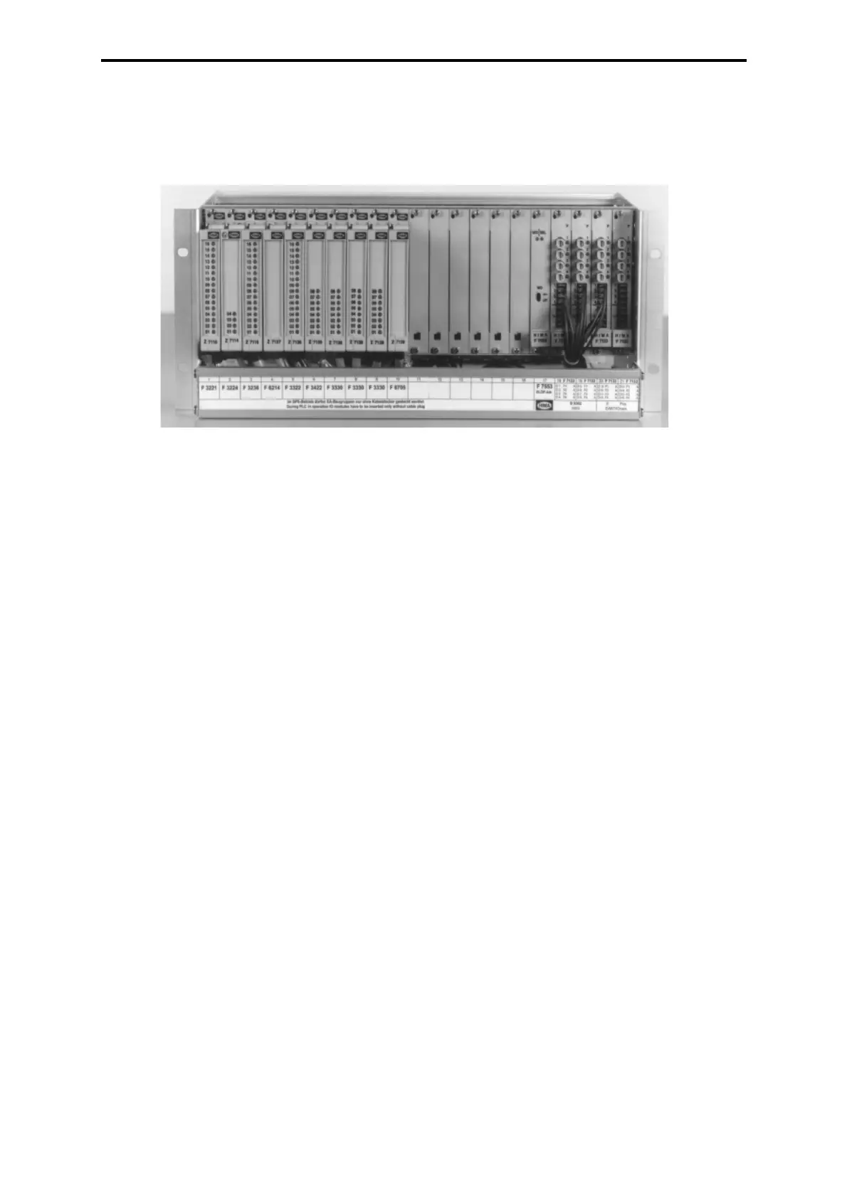
Figure 5: View of the I/O subrack 4 units high
4.3.1 The I/O Subrack
The I/O subrack fulfills the safety requirements of the SIL 3.
Slots 1 to 16 are provided for any type of input/output modules of the HIMA automation system.
Slot 17 is provided for the coupling module F 7553 for the I/O bus.
Slots 18 to 21 keep the power distribution modules F 7133. They are non-interactive and have
a fuse monitoring with failure signalization by an LED and a contact. The power distribution
module F 7133 can be used to fuse the I/O modules as well as the sensor and the actuator
circuits.
There is a cable tray under the input/output subrack. It is equipped with a receptacle for the
label which can be hinged to provide easy access to the cables.
4.3.2 24 VDC Power Supply and Distribution
Standard design: The 24 VDC power is distributed via a fuse and power distribution drawer.
For the input/output subracks max. 16 A back-up fuses are provided for L+. The power for the
input/output modules is fed in at the rear side of the power distribution modules F 7133 via
XG. 7/8/9/10.
Each I/O module is assigned to a fuse on the module F 7133 (refer also to the description of
the assembly kit B 9302).
The relation between the power distribution modules with 4 fuses each and the slots of the
I/O modules is as follows:
F 7133 in slot 18 supplies the I/O slots 1...4,
F 7133 in slot 19 supplies the I/O slots 5...8,
F 7133 in slot 20 supplies the I/O slots 9...12,
F 7133 in slot 21 supplies the I/O slots 13...16.
The supply of the I/O modules is made either via the cable plug on the front side or via the con-
nection already integrated in the I/O bus board (for (Ex)i modules and partly analog input mod-
ules).
The potential distributor XG. 11 is connected to the L- of the power distribution drawer. So all