The H51q System Family
17
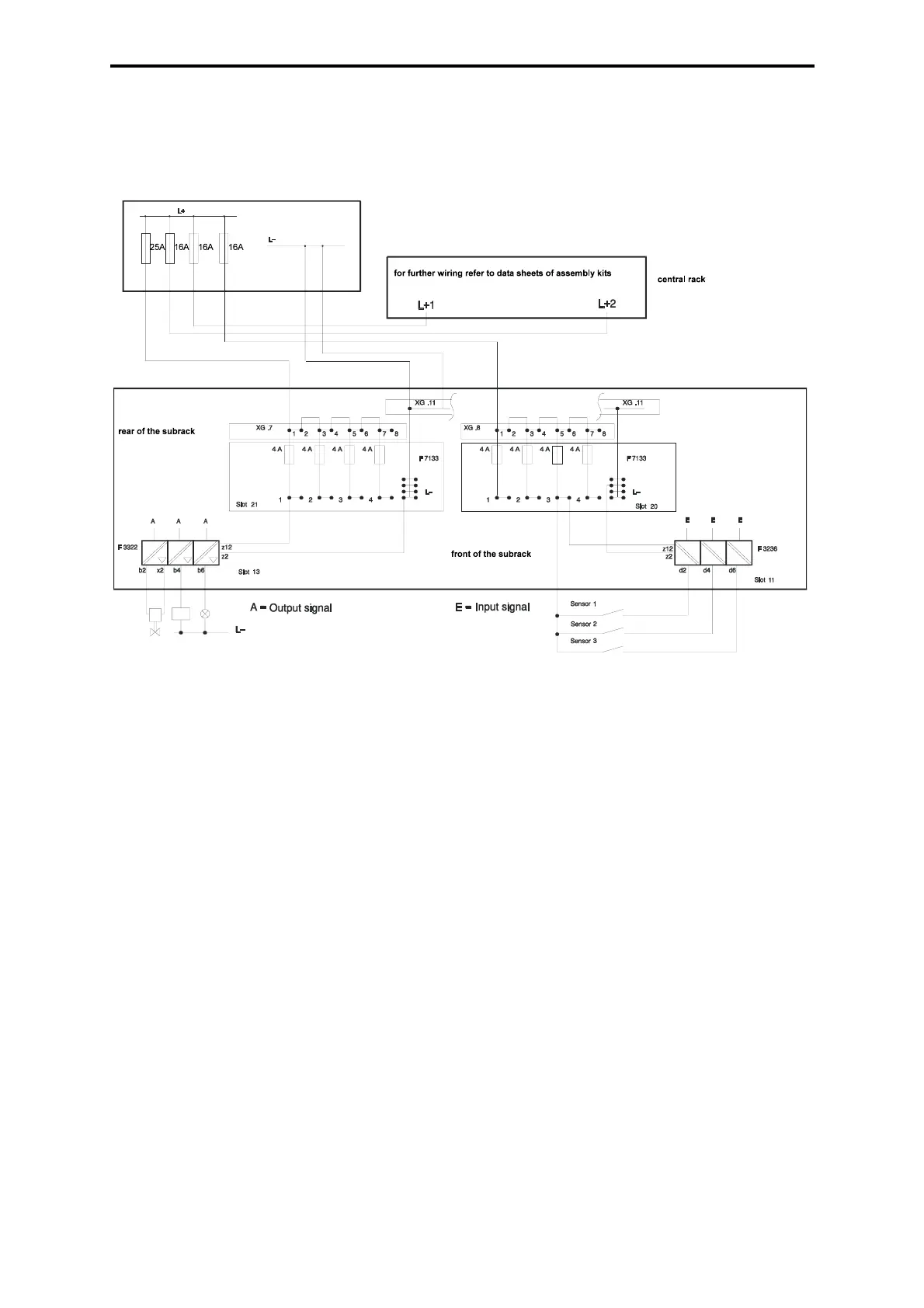
power distribution modules F 7133 are internal connected with L-. Via the front side of the pow-
er distribution modules the L- is also fed to the input/output modules via the cable plugs.
The circuit feeding of the sensors is fused by the front of the F 7133 module. The input module
and the appertaining sensors use the same power supply circuit of the power distribution mod-
ule F 7133.
Figure 6: Feeding and distribution 24 VDC
4.3.3 5 VDC Distribution
The 5 VDC system voltage for the I/O subracks is taken from the flat pin plugs of the distribu-
tors XG .2 and XG .3 on the rear side of the central rack in star shape.
The power is connected to the I/O subracks on the accordingly marked flat pin plugs XG .4 for
+5 VDC and XG .12 for GND on the rear side of the I/O subracks.
The power is internally distributed to the I/O modules via the bus board.
4.3.4 Extension of the 5 VDC Power Supply
If the power requirements of the 5 V circuits is > 18 A an additional power supply has to be
used. For this purpose the B 9361 assembly kit can be used which provides the possibility of
applying three power supplies F 7126 together with the monitoring module F 7131 in an addi-
tional subrack.
The 5 V output circuits of the additional power supply must not be switched in parallel with the
ones from the central rack. Apart from them they supply their own circuits. The reference poles
GND have to be connected together.
The power supply units of the additional power supply (assembly kit B 9361) emit monitoring
signals. These signals can be taken from the XG .1 terminal block on the rear side of the sub-
rack (see B 9361 assembly kit). They can be fed into the PLC via digital input modules. In the
logic of the PLC the signals are used to trigger an error message.